background image

Greensmaster Flex 18/21

Groomer

Page 8 – 9

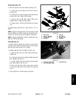
NOTE: The drive pulley has left handed threads. To
prevent cutting reel from turning when removing drive
pulley, block reel with piece of wood.

8. Use a 3/8” drive socket wrench to remove drive
pulley (item 17) from the cutting reel shaft.

9. Remove two (2) shoulder nuts (item 13) that secure
the groomer RH side plate to the cutting unit side plate.
Remove the groomer RH side plate.

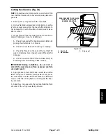
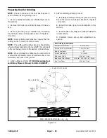
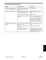
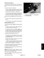
10.Remove the cap plug from LH side plate (Fig. 8).

NOTE: To prevent the grooming shaft from turning
when removing flange nut, use wrench on shaft flats to
hold shaft.

11. Remove the flange nut that secures the grooming
shaft to the LH side plate.

12.Pull the grooming reel from the LH side plate.

13.Inspect seals, bushings and bearings in side plates
for wear or damage. Replace components as needed.

Installation

1. Park mower on a level surface. Make sure engine is
OFF. Remove high tension lead from the spark plug.

2. Apply a light coating of grease to seal lips in RH and
LH side plates. Make sure that seals, bushings and
bearing are properly positioned in side plates.

3. Carefully place grooming reel assembly into the LH
side plate bearings taking care to not damage seal in
side plate. Thread flange nut onto the shaft threads but
do not fully tighten.

4. Carefully place RH side plate onto grooming shaft
taking care not to damage seals in side plate. Position
side plate to the cutting unit. Secure side plate with two
(2) shoulder nuts (item 13).

NOTE: The drive pulley has left handed threads. To
prevent cutting reel from turning when installing drive
pulley, block reel with piece of wood.

5. Apply a light coating of grease to drive pulley hub tak-
ing care to not get grease on belt surface. Install and
tighten drive pulley onto the reel shaft.

6. Align splines of driven pulley to grooming shaft and
install pulley onto the shaft. Thread flange nut onto the
shaft threads but do not fully tighten.

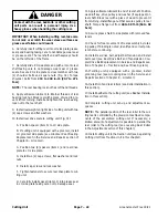
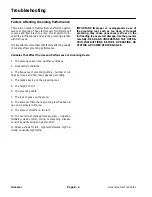
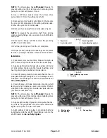
1. Cap 

screw

2.  Front roller shaft

3. Grooming 

shaft

4. Locknut/spring 

washer

Figure 7

4

3

1

2

1.  Roller retaining cap screw
2. Cap 

plug

Figure 8

1

2

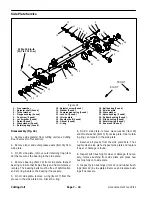
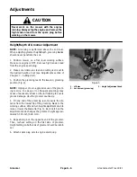
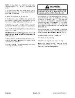
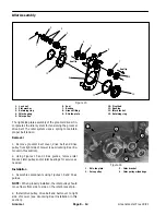
1.  RH side plate
2. Drive 

pulley

3. Driven 

pulley

Figure 9

1

3

2

Groomer

Summary of Contents for 04022 Greensmaster Flex 21

Page 1: ...ble on the internet at www toro com or by sending complete Model and Serial Number to The Toro Company Attn Technical Publications 8111 Lyndale Avenue South Minneapolis MN 55420 1196 The Toro Company reserves the right to change product specifications or this publication without notice This safety symbol means DANGER WARNING or CAUTION PERSONAL SAFETY INSTRUC TION When you see this symbol carefull...

Page 2: ...Greensmaster Flex 18 21 This page is intentionally blank ...

Page 3: ... 4 3 Service and Repairs 4 5 Chapter 5 Electrical System Wiring Schematic 5 2 Special Tools 5 3 Troubleshooting 5 5 Component Testing 5 6 Service and Repairs 5 8 Chapter 6 Chassis and Controls Specifications 6 2 General Information 6 3 Service and Repairs 6 4 Chapter 7 Cutting Unit Specifications 7 2 General Information 7 3 Special Tools 7 4 Factors That Affect Quality Of Cut 7 6 Adjustments 7 8 S...

Page 4: ...Greensmaster Flex 18 21 This page is intentionally blank ...

Page 5: ...Greensmaster Flex 18 21 Page 1 1 Safety Chapter 1 Safety Table of Contents SAFETY INSTRUCTIONS 2 Before Operating 2 While Operating 3 Maintenance and Service 3 SAFETY AND INSTRUCTION DECALS 4 Safety ...

Page 6: ...ds safety devices and decals in place If a shield safety device or decal is malfunctioning illeg ible or damaged repair or replace it before operating the machine 5 Always wear substantial shoes Do not operate ma chine while wearing sandals tennis shoes or sneakers Do not wear loose fitting clothing which could get caught in moving parts and cause personal injury 6 Wearing safety glasses safety sh...

Page 7: ...is not to be used for an extended period of time Also close fuel shut off valve if machine is to be transported on a trailer or in a vehicle Maintenance and Service 1 Before servicing or making adjustments to the ma chine stop the engine and wait for all machine move ment to stop Remove the spark plug wire from the spark plug to prevent accidental starting of the engine 2 To make sure entire machi...

Page 8: ...fety decals and instructions are easily visible to the operator and are located near any area of potential dan ger Replace any decal that is damaged or lost Decal part numbers are listed in your Parts Catalog Order re placement decals from your Authorized TORO Distribu tor ...

Page 9: ...eners 5 Other Torque Specifications 6 Conversion Factors 6 Product Records Insert Operator s Manual and Parts Catalog for your Greensmaster Flex 18 or Flex 21 at the end of this sec tion Additionally if any optional equipment or accesso ries have been installed to your machine insert the Installation Instructions Operator s Manuals and Parts Catalogs for those options at the end of this chapter Ma...

Page 10: ...0 09375 Greensmaster Flex 18 21 Page 2 2 Product Records and Maintenance Equivalents and Conversions ...

Page 11: ...ng torque feature e g Nylock nut hardness of the surface underneath the fastener s head or similar condition which affects the installation As noted in the following tables torque values should be reduced by 25 for lubricated fasteners to achieve the similar stress as a dry fastener Torque values may also have to be reduced when the fastener is threaded into aluminum or brass The specific torque v...

Page 12: ...C 16 2 16 2 22 3 30 3 41 4 43 5 58 7 3 8 24 UNF 17 2 18 2 24 3 35 4 47 5 50 6 68 8 7 16 14 UNC 27 3 27 3 37 4 50 5 68 7 70 7 95 9 7 16 20 UNF 29 3 29 3 39 4 55 6 75 8 77 8 104 11 1 2 13 UNC 30 3 48 7 65 9 75 8 102 11 105 11 142 15 1 2 20 UNF 32 4 53 7 72 9 85 9 115 12 120 12 163 16 5 8 11 UNC 65 10 88 12 119 16 150 15 203 20 210 21 285 28 5 8 18 UNF 75 10 95 15 129 20 170 18 230 24 240 24 325 33 3...

Page 13: ...t lb 90 10 N m 93 10 ft lb 126 14 N m M16 X 2 0 166 17 ft lb 225 23 N m 229 23 ft lb 310 31 N m M20 X 2 5 325 33 ft lb 440 45 N m 450 46 ft lb 610 62 N m NOTE Torque values may have to be reduced when installing fasteners into threaded aluminum or brass The specific torque value should be determined based on the fastener size the aluminum or base material strength length of thread engagement etc N...

Page 14: ...00 in lb Wheel Bolts and Lug Nuts Thread Size Recommended Torque 7 16 20 UNF Grade 5 65 10 ft lb 88 14 N m 1 2 20 UNF Grade 5 80 10 ft lb 108 14 N m M12 X 1 25 Class 8 8 80 10 ft lb 108 14 N m M12 X 1 5 Class 8 8 80 10 ft lb 108 14 N m For steel wheels and non lubricated fasteners Thread Cutting Screws Zinc Plated Steel Thread Size Threads per Inch Baseline Torque Size Type A Type B Baseline Torqu...

Page 15: ...ne Table of Contents SPECIFICATIONS 2 INTRODUCTION 3 GENERAL INFORMATION 3 Operator s Manual 3 ADJUSTMENTS 4 Throttle Cable Adjustment 4 SERVICE AND REPAIRS 5 Cooling System 5 Ignition Components 5 Spark Plug 6 Engine 8 KAWASAKI FE120 SERVICE MANUAL Engine ...

Page 16: ...ical flyweight Low Idle Speed no load 2400 100 RPM High Idle Speed no load 3600 100 RPM Direction of rotation Counter clockwise facing PTO shaft Fuel Unleaded automotive grade gasoline Fuel Tank Capacity 2 6 U S qt 2 5 l Engine Oil See Operator s Manual Lubrication System Splash type Oil Capacity 0 63 U S qt 0 6 l Air Cleaner Dual element Ignition System Transistorized flywheel magneto with igniti...

Page 17: ...se of some specialized test equipment is explained However the cost of the test equipment and the special ized nature of some repairs may dictate that the work be done at an engine repair facility Service and repair parts for Kawasaki engines are sup plied through your local Toro distributor Be prepared to provide your distributor with the Toro model and serial number General Information Operator ...

Page 18: ...s in the FAST position and the governor lever is against the high idle speed screw 5 Tighten throttle cable screw to secure the throttle cable to the governor lever 6 After cable adjustment connect spark plug wire to spark plug start engine and check engine speed with a tachometer A Low idle speed should be 2300 to 2500 RPM Ad just low idle speed screw in or out to attain the correct low idle spee...

Page 19: ...taminate the fuel system 2 Clean cooling fins on cylinder and cylinder head Re move engine cylinder shroud from engine for more thor ough cleaning Fig 2 3 Clean blower housing of dirt and debris Fig 3 Re move housing if necessary IMPORTANT Never operate engine without the blower housing installed Overheating and engine damage will result 4 Make sure blower housing and or engine cylinder shroud are...

Page 20: ... of the engine Use the chart on the following page as a guide to determine possible problems with the engine 3 Inspect the spark plug IMPORTANT Replace a cracked fouled or dirty spark plug Do not sand blast scrape or clean spark plug electrodes because engine damage could re sult from grit entering cylinder 4 Set electrode gap from 0 028 to 0 032 0 7 to 0 8 mm Install correctly gapped spark plug i...

Page 21: ...nsulator and in the bore Excessive oil entering the combustion chamber past worn valve guides valve stems rings piston and or cylinder bore Replace spark plug Has gray or light tan deposits on the firing tip Light gray or white insulator with small gray brown or black spots Electrode has a bluish burnt appearance May be caused by engine overheating loose spark plug wrong fuel type plug heat range ...

Page 22: ...et screw 4 used 17 Cap screw 18 Lock washer 2 used 19 Flat washer 20 Flat washer 21 Lock nut 22 Cap screw 23 Isolator mount 2 used 24 Jam nut 2 used 25 Tab washer 2 used 26 Hourmeter 27 Lock washer 2 used 28 Muffler guard 29 Cap screw 4 used 30 Muffler guard bracket 2 used 31 Square key 32 Washer head screw 4 used 33 Flat washer 4 used 34 Hourmeter mounting clip FRONT RIGHT 1 17 18 19 3 4 16 32 28...

Page 23: ...from wire harness connectors C Disconnect wire harness ground wire from en gine by removing cap screw and lock washer 6 Remove engine from the engine base Fig 6 A Remove four 4 flange nuts that secure gearbox assembly to set screws on engine crankcase cover B Support gearbox between mower frame and gearbox flange C Remove four 4 cap screws flat washers and flange nuts that secure engine to engine ...

Page 24: ...ed to mesh engine gear teeth with gearbox input gears E Install and finger tighten four 4 flange nuts that secure gearbox assembly to set screws on engine crankcase cover F Install four 4 cap screws with flat washers through the engine and engine base Put flange nut on each cap screw and hand tighten G Fully tighten flange nuts that secure gearbox as sembly to engine and then tighten flange nuts t...

Page 25: ... Manual 3 Gearbox Seals 3 SERVICE AND REPAIRS 5 Reel Drive and Transmission Coupler Drive Belt Replacement 5 Reel Drive Assembly 6 Reel Drive and Transmission Coupler Bearing Housing 7 Traction Drive Belt Replacement 10 Traction Drive Idler Pulley and Bearings 11 Traction Drum Assembly 12 Gearbox 16 Gearbox Service 18 Differential Service 22 Traction and Reel Drive System ...

Page 26: ...lts Gearbox Fluid Dexron III Automatic Transmission Fluid or equivalent Gearbox Fluid Capacity 2 9 U S qt 2 8 l Differential Integral in Gearbox Assembly Parking Brake Band Drum in gearbox Traction Drum Dual Cast Aluminum 7 5 inch 19 1 cm Diameter Cutting Reel Drive Gear Driven Countershaft in gearbox with Cone Wet Clutch Flexible Coupler Shaft Used in Reel Drive System Gearbox to Reel Drive has 8...

Page 27: ...ter machine Refer to the Operator s Manual for additional information when ser vicing the machine Gearbox Seals The Greensmaster Flex 18 and Flex 21 use cannister seals in the gearbox This type of seal is internally lubri cated and like other seals could normally have a light lubricant film evident at the seal lips Cannister seals will also cause a slightly higher amount of drag than other seal ty...

Page 28: ...Greensmaster Flex 18 21 Traction and Reel Drive System Page 4 4 This page is intentionally blank ...

Page 29: ...left side Fig 2 3 Loosen the two 2 bearing housing mounting nuts 4 Pivot bearing housing to loosen belt tension Re move drive belt from the two pulleys Installation 1 Park machine on a level surface Make sure engine is OFF Remove spark plug wire from the spark plug 2 Place a new drive belt onto the two pulleys 3 Adjust drive belt tension see Operator s Manual 4 Install belt cover to machine and se...

Page 30: ...lug 29 Spacer 30 Spacer 31 Lock washer 32 Cap screw 33 Pulley 27 tooth Figure 3 3 1 2 3 4 5 6 7 8 7 10 11 15 16 17 15 12 9 13 FRONT RIGHT Antiseize Lubricant 100 in lb 11 3 N m 1 3 2 4 5 6 7 8 7 10 11 33 13 16 9 15 17 17 17 18 18 12 12 12 14 14 14 19 20 21 22 23 25 24 26 27 28 29 30 31 32 40 to 50 ft lb 54 to 68 N m 40 to 50 ft lb 54 to 68 N m 40 to 50 ft lb 54 to 68 N m 40 to 50 ft lb 54 to 68 N ...

Page 31: ...ove flange nuts and washers from carriage screws that secure bearing housing to plate assembly 6 Slide bearing housing with shaft and coupler away from the frame Bearing Housing Disassembly NOTE When removing flex coupler from shaft do not mar outer surface of coupler e g grasping with pliers or mounting in vise as coupler may be damaged and fail prematurely 1 Push spring pin from flex coupler and...

Page 32: ...rews Do not fully tighten flange nuts at this time 4 Position spacer onto shaft Place woodruff key into shaft keyslot 5 Apply antiseize lubricant to the bore of the pulley and install pulley onto shaft A Left side pulley uses a pulley washer B Right side pulley should be installed with the flange outward NOTE Do not grasp hex shaft when tightening flange nut that secures pulley as flex coupler may...

Page 33: ...Greensmaster Flex 18 21 Traction and Reel Drive System Page 4 9 This page is intentionally blank Traction and Reel Drive System ...

Page 34: ...idler bracket to frame Fig 10 Pivot the idler pulley away from the drive belt to loosen belt tension Fig 11 5 Remove traction drive belt from both pulleys Installation 1 Park machine on a level surface Make sure engine is OFF Remove spark plug wire from the spark plug 2 Place traction drive belt onto both pulleys 3 Adjust traction drive belt tension see Operator s Manual 4 Install traction drive b...

Page 35: ... outer bearing race only B Install pulley assembly onto idler shaft pressing on inner bearing race 3 Position idler assembly using cap screw and shoul der nut Figs 13 and 14 Tighten shoulder nut Check that idler assembly can pivot freely after tightening shoulder nut 4 Install cap screw and tab washer that positions the idler bracket to the side plate of the mower Fig 14 Make sure that washer tab ...

Page 36: ...wn 22 Cap screw 8 used 23 Cap screw 2 used 24 Flange nut 2 used 25 Bearing flangette 4 used 26 Traction drive pulley 2 used 27 Pulley sleeve 2 used 28 Seal 2 used 29 Tab washer 2 used 30 Cap screw 2 used 31 Lock washer 8 used 32 Carriage screw 10 used 33 Flange nut 12 used 34 Gearbox assembly 35 Set screw 4 used Figure 15 FRONT RIGHT 100 in lb 11 3 N m Antiseize Lubricant 40 to 50 ft lb 54 to 68 N...

Page 37: ...ction drum assembly 9 Locate and remove drum spacer item 41 from each side of traction drum assembly 10 Remove traction drum assembly from the mower 11 If necessary remove bearing flangettes item 10 and bearings item 11 from machine frame Traction Drum Disassembly Fig 15 1 Remove four 4 cap screws item 22 and lock wash ers item 34 that secure each traction drum to drum hub spindle assembly Separat...

Page 38: ... sure that extended race of bearings is positioned to the outside of the frame 3 Pivot mower back and position traction drum assem bly under the mower Lower mower onto traction drum 4 Position drum spacers to sides of drum 5 Insert bar stock or other suitable tool through spokes of drum to keep drum from turning NOTE The left side drum shaft has left hand threads Fig 16 6 Apply antiseize lubricant...

Page 39: ...Greensmaster Flex 18 21 Traction and Reel Drive System Page 4 15 This page is intentionally blank Traction and Reel Drive System ...

Page 40: ...ve belt covers and belts from both sides of mower see Traction Drive Belt Replace ment in this section 6 Remove flange nut that secures traction drive pulley Fig 19 on both sides of mower Remove pulley and woodruff key from both sides 7 Loosen set screws that secure extended race bear ings to gearbox axles Fig 19 8 Remove carriage bolts flange nuts and flat washers that retain bearing flangettes t...

Page 41: ... secure gearbox to engine Fig 20 7 Secure extended race bearings and bearing flan gettes to frame with carriage bolts flat washers and flange nuts 8 Check bearing alignment by rotating the long gear box axle shaft Shaft should rotate easily if alignment is correct 9 Tighten the bearing set screws to secure the bear ings to the gearbox axles Torque set screws from 40 to 50 in lb 4 5 to 5 7 N m 10 A...

Page 42: ...53 Traction band assembly 54 Traction shaft 55 Ball bearing 56 Retaining ring 4 used 57 Differential assembly traction drive 58 Gasket 59 Gearbox cover 60 Keyed bushing 61 E ring 62 Traction drive lever 63 Socket head screw 2 used 64 Socket head screw 4 used 65 Drive shaft plate assembly 66 Internal lock washer 67 Oil seal red orange color 68 O ring 69 Dowel pin 70 Wave washer 71 Hub 72 Retaining ...

Page 43: ...t 7 Carefully remove traction shaft from the gearbox tak ing care to not distort traction band Fig 24 Note On Flex 21 if gearbox is still attached to engine traction le ver on engine side of gearbox must be loosened and re moved as traction shaft is removed from gearbox 8 Slide differential assembly from gearbox Fig 24 9 Pull planetary assembly with parking brake band and shaft from gearbox Fig 24...

Page 44: ...ter installation 2 Thoroughly apply grease to seal lips in both the gear box base and cover 3 If clutch shaft was disassembled use Figure 26 as a guide to install components to clutch shaft Install clutch shaft assembly into gearbox base and rotate clutch fork to plunger hub Place thrust washer on cover end of shaft 4 Attach link to fork shaft and bellcrank Secure with two 2 retaining rings 5 Lubr...

Page 45: ... and washers in remaining holes in gearbox cov er Torque gearbox fasteners from 120 to 140 in lb 13 6 to 15 8 N m in the sequence shown in Figure 29 14 Place traction drive lever onto gearbox shaft noting location of alignment splines on shaft and lever Mount traction lever with cable boss outward Fig 30 Secure lever with cap screw and lock nut Parking brake lever installation should be done with ...

Page 46: ...ial assembly and drive out roll pin that locates gear shaft Discard roll pin 3 Remove gear shaft two 2 thrust washers and two 2 driven bevel gears 4 Remove retaining ring from each axle Discard re taining rings 5 Pull each axle free from drive bevel gear washer and input gear housing Note that axle washers are different from washers used on gear shaft Inspection Fig 31 1 Clean all differential com...

Page 47: ...l gears and rotate axle to move them into their correct position 3 Place a washer between input gear housing and each driven bevel gear Install gear shaft with grooved end located at roll pin hole 4 Check gear and shaft alignment by rotating one axle The other axle should turn in the opposite direction with out any binding Once free axle movement is checked install new roll pin to secure gear shaf...

Page 48: ...Greensmaster Flex 18 21 Traction and Reel Drive System Page 4 24 This page is intentionally blank ...

Page 49: ...f Contents WIRING SCHEMATIC 2 SPECIAL TOOLS 3 TROUBLESHOOTING 5 Starting Problems 5 COMPONENT TESTING 6 Ignition System Operation 6 Ignition Coil 6 Interlock Module and Switch 7 Lighting Coil 7 SERVICE AND REPAIRS 8 Interlock Switch 8 Operator Presence Switch Optional 9 Electrical System ...

Page 50: ...SWITCH IGNITION COIL BLACK BLACK Kawasaki FE120 Engine ON OFF SWITCH is open in the ON position INTERLOCK SWITCH is closed when traction lever is in NEUTRAL HIGH TENSION LEAD FLYWHEEL RED CONNECTOR LIGHTING COIL YELLOW YELLOW ORANGE HOURMETER BLACK CONNECTOR RED OPTIONAL OPERATOR PRESENCE SWITCH OPERATOR PRESENCE SWITCH is closed when bail is against handle ...

Page 51: ...nt is not allowed through the meter This excess current can cause damage to circuits not designed to carry it Figure 1 Skin Over Grease Toro Part Number 505 165 Special non conductive grease which forms a light pro tective skin to help waterproof electrical switches and contacts Figure 2 Dielectric Gel Toro Part Number 107 0342 Dielectric gel should be used to prevent corrosion of connection termi...

Page 52: ...rical System Spark Tester Toro Part Number TOR4036 For testing electronic ignitions Saves time because you will know if the ignition is causing the problem on a non starting engine The tester determines if ignition spark is present Figure 4 ...

Page 53: ...3 Engine for additional engine igni tion system troubleshooting information Starting Problems Problem Possible Causes Correction Engine will not start ON OFF switch is in the OFF position or is grounded Ignition spark plug wire is not connected to spark plug Electrical wires are loose or damaged Interlock switch is not adjusted or is faulty Interlock module is faulty Turn switch to ON or replace s...

Page 54: ...th engine not running remove spark plug wire from the spark plug and connect it to the spark tester see Special Tools in this chapter 2 Connect spring clip of tester to a good unpainted ground on the engine block 3 Make sure ON OFF switch is in the ON position 4 Pull the engine starter rope and observe the spark tester Visible and audible sparks should be produced 5 If visible and audible sparks a...

Page 55: ...to wiring harness 3 With engine ON OFF switch in the ON position at tempt to start the engine If the engine does not start check the interlock module using the following steps A Disconnect red wire male connector where it connects to the black wire leading to the ignition coil Fig 5 B Attempt to start the engine The engine should start C Ground the red wire male connector to the en gine block and ...

Page 56: ... after tighten ing fasteners The traction lever must not contact the switch 6 Engage traction lever and verify that the switch opens no continuity Removal 1 Disconnect switch from the wires leading from the In terlock module 2 Remove fasteners and spacers that mount switch to control bracket on handle Fig 7 Remove switch from bracket Installation 1 Position switch to control bracket with fasteners...

Page 57: ...ly closed termi nal is not used Testing Using a multimeter the operator presence switch can be tested as follows 1 With the bail released away from the handle there should be no continuity between the two terminals used on the Operator Presence Kit switch Fig 8 2 With the bail held against the handle there should be continuity between the same two terminals Adjustment 1 Mount operator presence swi...

Page 58: ...Greensmaster Flex 18 21 Page 5 10 Electrical System This page is intentionally blank ...

Page 59: ...ents SPECIFICATIONS 2 GENERAL INFORMATION 3 Operator s Manual 3 SERVICE AND REPAIRS 4 Handle Assembly 4 Parking Brake Cable Replacement 6 Traction Control Cable Replacement 7 Reel Control Cable Replacement 8 Throttle Cable Replacement 9 Transport Wheels Optional 10 Kickstand 12 Chassis and Controls ...

Page 60: ...Greensmaster Flex 18 21 Page 6 2 Chassis and Controls Specifications Item Description Transport Wheel Optional Tire Pressure 12 to 15 PSI 0 83 to 1 04 bar ...

Page 61: ...tion Operator s Manual The Operator s Manual provides information regarding the operation adjustment procedures and general maintenance for your Greensmaster machine Refer to the Operator s Manual for additional information when servicing the machine Chassis and Controls ...

Page 62: ...el clutch cable 21 Wiper 22 Control bracket 23 Reel lever pin 24 Friction washer 2 used 25 Dowel pin 26 Throttle cable 27 Cap screw 28 Cap screw 3 used 29 Throttle lever 30 Support rod 31 Lock nut 4 used 32 Spacer 3 used 33 Retaining ring 3 used 34 Brake cable 35 Lock nut 36 Brake knob red 37 Flange head screw 38 Lock nut 2 used 39 Cap screw 4 used 40 Cap screw 41 Detent spring 42 Washer head scre...

Page 63: ... end of the handle Fig 3 5 Remove handle from frame Handle Installation 1 Slide handle ends through the holes in the handle arms with grommets Install handle to the frame using cap screw pivot pin and flange nut on each side 2 Attach and adjust A Reel control traction and parking brake cables see Cable Replacement in this section B Throttle cable see Throttle Cable Replacement in this section C In...

Page 64: ... cable from the bracket 6 Remove brake cable from the machine Installation 1 Secure brake cable eyelet to the brake lever on the machine handle with flange head screw spacer and lock nut Fig 5 2 Position cable to the brake bracket and install retain ing ring Fig 5 3 Route brake cable to the gearbox assembly Install brake cable to the gearbox and gearbox brake lever as follows Fig 4 A Position brak...

Page 65: ...ove cable from traction lever assembly 5 Remove traction cable from the machine Installation 1 Secure traction cable spring to the traction lever as sembly Fig 7 A Install cable spring to pin on traction lever assem bly and secure with retaining ring B Secure the cable housing to the control bracket with retaining ring 2 Route traction cable to the gearbox Install cable to the gearbox as follows F...

Page 66: ...ring from reel control lever 5 Remove reel control cable from the machine Installation 1 Secure reel control cable to the reel control lever Fig 9 A Hook cable spring to reel control lever B Secure the cable housing to the control bracket with retaining ring 2 Route reel control cable to the gearbox Install cable to the gearbox as follows Fig 8 A Secure cable eyelet to the reel control bellcrank w...

Page 67: ...ck et B Unhook cable end from throttle lever 6 Remove throttle cable from the machine Installation 1 Connect throttle cable to the throttle lever Snap throttle cable housing to the control bracket Fig 12 2 Position console to handle and secure console with four 4 screws 3 Route throttle cable to the governor lever 4 Install cable to the governor lever as follows Fig 10 A Insert throttle cable into...

Page 68: ...Optional 1 Cap screw 3 used 2 Lock washer 3 used 3 Shallow rim 4 Tire 5 Hub 6 Wheel retaining lever 7 Torsion spring 8 Shoulder screw 2 used 9 Cap screw 4 used 10 Deep rim 11 Inner tube 12 Hub bushing 13 Flange nut 4 used Figure 13 1 2 3 4 5 6 7 8 9 10 11 12 13 Loctite 242 ...

Page 69: ...shoulder screws were removed from hub apply Loctite 242 or equivalent to threads of shoulder screws Secure torsion spring and retaining lever to the hub with shoulder screws 2 Assemble tire tube and deep rim 3 Install shallow rim into the tire Align and secure shal low rim to the deep rim with four 4 cap screws and flange nuts Tighten fasteners 4 Install hub into deep rim Secure hub to deep rim wi...

Page 70: ...e torsion spring Push the torsion spring down and in to release spring tension Fig 17 4 Remove flange nuts cap screws flat washers spacers and torsion spring from the kickstand and frame Note that long spacer and torsion spring is on the left side of the machine and short spacer is on the right 5 Remove kickstand from the frame Installation Fig 16 1 Make sure machine is parked on a level surface a...

Page 71: ...g Cutting Unit From Traction Unit 3 SPECIAL TOOLS 4 FACTORS THAT CAN AFFECT QUALITY OF CUT 6 ADJUSTMENTS 8 Leveling Rear Roller 8 SERVICE AND REPAIRS 9 Backlapping 9 Bedbar 10 Bedknife Service 12 Bedbar Adjuster Service 14 Rollers 16 Roller Service 18 Cutting Reel 20 Cutting Reel Service 23 Side Plate Service 24 Preparing Reel for Grinding 26 Cutting Unit ...

Page 72: ...of cut range is 1 16 to 19 64 inch 1 6 to 7 5 mm depending on type of bedknife installed Effective HOC may vary depending on turf conditions type of bedknife rollers and attachments installed CLIP 0 14 inch 3 56 mm with 11 blade reel 0 19 inch 4 83 mm with optional 8 blade reel BEDKNIFE AND BEDBAR Single edged high carbon steel bedknife hardened to RC 48 54 A cast iron bed bar is fastened to the c...

Page 73: ...nto frame hole above kickstand mounting bolt to lock kickstand in place Fig 1 3 Remove grass basket if installed 4 Remove two 2 cap screws and flat washers secur ing cutting unit pitch arms to traction unit front frame Fig 2 5 Rotate pitch arms forward and rest traction unit on locked kickstand 6 Pull cutting unit forward about 2 inches 51 mm and then to the right to disengage the transmission cou...

Page 74: ...while keeping the operator s hands at a safe distance from the rotating reel Figure 5 Bedknife Screw Tool Toro Part Number TOR510880 This screwdriver type bit is made to fit Toro bedknife at taching screws Use this bit with a 3 8 drive torque wrench to secure the bedknife to the bedbar DO NOT use an air or manual impact wrench with this tool Figure 6 Roller Bearing Installation Tools Washers and s...

Page 75: ...R4105 is an alternative to using washers and spacers listed above Figure 8 Sleeve Driver Toro Part Number TOR4107 Used to drive the wear sleeve into position on the cutting reel shaft Figure 9 Sleeve Driver and Bearing and Seal Installer Set Toro Part Number TOR4108 Set includes both TOR4105 and TOR4107 in a plastic storage case with foam inserts Figure 10 Cutting Unit ...

Page 76: ... reel to remove taper and or rifling Grind bedknife to sharpen and or remove rifling The most common cause of rifling is bedknife to reel contact that is too tight A new bedknife must be ground or backlapped after installation to the bedbar Bedknife to reel adjustment Check bedknife to reel contact daily The bedknife must have light contact across the entire reel No contact will dull the cutting e...

Page 77: ...e freely Repair roller bearings if necessary see Roller Service in Service and Repairs section of this chapter Traction speed Check maximum governed engine speed Adjust engine to specifications if necessary see Adjustments section in Chapter 3 Engine The traction drive belts may be loose or worn Check the condition of the traction belts Adjust or replace traction drive belts as necessary Groomer r...

Page 78: ...Fig 11 3 Back off the spring tension lock nuts until the washer is no longer tensioned against the bedbar Fig 11 4 Loosen but do not remove two 2 cap screws and lock nuts that secure the grass shield to the side plates Fig 12 5 Loosen but do not remove four 4 shoulder bolts that secure the side plates to the crossmember Fig 12 6 Adjust the position of the side plates to parallel the rear roller an...

Page 79: ... the reel when backlapping Never use a short handled paint brush for applying lapping compound Part Number TOR299100 backlapping brush assembly see Special Tools is available from your local Authorized Toro Distributor 5 Backlap according to procedure in TORO Sharpen ing Reel and Rotary Mowers Manual Form No 80300 SL NOTE For a better cutting edge run a file across the front face of the bedknife w...

Page 80: ...move spark plug wire from the engine spark plug 2 On both sides of cutting unit loosen bedbar adjuster screw by turning screw counterclockwise Fig 15 3 Back off the spring tension lock nut until the washer is no longer tensioned against the bedbar Fig 15 4 Loosen flange nuts securing the bedbar pivot bolts on both sides of the cutting unit Remove both pivot bolts with flange nut nylon washer and m...

Page 81: ...late 6 Slide each bedbar pivot bolt assembly through side plate and washers and then thread into bedbar After both bedbar bolts have been installed torque bedbar pivot bolts from 190 to 240 in lb 21 5 to 27 1 N m 7 Tighten flange nuts until all end play is removed from outside washers Do not overtighten flange nuts After tightening flange nuts inner washers still might rotate 8 Tighten spring tens...

Page 82: ... Bedknife Grinding Since there can be variations in the mounting surface of the bedbar a new bedknife will not be perfectly flat after it is installed It is therefore necessary to grind a new bedknife after installing it to the bedbar Follow the exist ing bedknife angle and grind only enough to make sure the top surface is true Fig 19 The bedbar needs to be removed from mower for proper bedknife g...

Page 83: ...Greensmaster Flex 18 21 Page 7 13 Cutting Unit This page is intentionally blank Cutting Unit ...

Page 84: ...ve washer item 4 from adjuster shaft and remove adjuster shaft from cutting unit frame 6 Inspect flange bushings item 2 and remove from cutting unit frame if necessary 7 If the detent item 7 is damaged remove it from the cutting unit frame by removing the cap screw item 9 and lock washer item 8 Installation Fig 21 1 If the detent item 7 was removed secure detent to the cutting unit frame with cap ...

Page 85: ...Greensmaster Flex 18 21 Page 7 15 Cutting Unit This page is intentionally blank Cutting Unit ...

Page 86: ... 7 Lock nut 2 used 8 Height of cut washer 2 used 9 Height of cut arm 2 used 10 Roller spacer 2 used 11 Plow bolt 2 used 12 Cap screw 2 used 13 Front roller 14 Bearing lock 2 used per roller 15 V ring 2 used per roller 16 Seal 2 used per roller 17 Bearing 2 used per roller 18 Roller shaft Figure 22 FRONT RIGHT 1 10 3 2 4 5 11 6 7 8 9 12 13 14 15 16 17 18 18 17 16 15 14 Antiseize Lubricant ...

Page 87: ...oller from retainer that remains se cured to cutting unit side plate Roller Installation Fig 22 1 To install front roller A Insert one end of front roller into height of cut arm that is secured to cutting unit side plate B Slide second height of cut arm onto front roller shaft Secure height of cut arm to side plate with height of cut washer and lock nut C If equipped with groomer secure groomer si...

Page 88: ...and remove bearing lock nut from each end of roller shaft 3 Remove v ring from each end of roller 4 Carefully inspect seating surface and threads of bearing lock nuts Replace lock nut if any damage is found 5 Loosely secure roller assembly in bench vise and lightly tap one end of roller shaft until seal and bearing are removed from roller cavity in the opposite end of the roller Remove second seal...

Page 89: ...ssembly wash ers bottom out against the roller housing Remove nuts assembly washers and assembly spacers from roller shaft 3 If tool TOR4105 see Special Tools is available install seals and bearings with tool TOR4105 as follows A Position a new bearing and tool TOR4105 onto each end of the roller shaft B Tighten tools until the bearings are fully seated into each end of the roller Remove tool from...

Page 90: ...rk bench DANGER Contact with the reel bedknife or other cutting unit parts can result in personal injury Use heavy gloves when handling the cutting reel 2 Remove bedbar from the cutting unit see Bedbar Removal in this section 3 If cutting unit is equipped with a groomer remove grooming reel see Grooming Reel in the Service and Repairs section of Chapter 8 Groomer 4 Remove belt cover and reel drive...

Page 91: ... pitch arm from crossmember and grass shield 14 Refer to Cutting Reel Service in this section for infor mation on reel inspection and wear sleeve and v ring seal service Cutting Reel Installation Fig 29 1 Use a flat level surface or a stable work bench to install cutting reel 2 If separated attach LH side plate to crossmember with two 2 shoulder bolts and square nuts Fig 32 Torque shoulder bolts f...

Page 92: ...hers and lock nuts E Install cap screw and lock washer F Tighten fasteners to secure reel drive plate to cut ting unit G Carefully install spacer item 12 into grease seal in LH side plate taking care not to damage seal 11 Apply antiseize lubricant to end of reel shaft Position woodruff key drive pulley and washer if equipped on reel shaft Block reel with a piece of wood to prevent it from turning ...

Page 93: ...eel blades for bending or cracking C Check the threads on the ends of the reel shaft for wear or damage Also inspect woodruff keyslot for damage D Check the service limit of the reel diameter see Preparing Reel for Grinding in this section IMPORTANT During installation do not nick or scratch the wear sleeve surface as grease seal fail ure could result 4 Apply grease to reel shaft to ease wear slee...

Page 94: ...val in this section 2 Remove inner and outer grease seals item 16 from side plate 3 On RH side plate remove outer retaining ring item 24 that secures the bearing in the side plate 4 Remove bearing item 18 from side plate Inspect bearing to insure that it spins freely and has minimal ax ial play The bearing balls must be free of deformation and scoring Replace the bearing if necessary 5 On LH side ...

Page 95: ...ng item 24 into side plate groove 5 Pack the inner cavity of seals item 16 with Mobil High Temperature XHP 222 grease or equivalent Also fill side plate cavity between installed bearing and both seal locations 75 to 95 full with Mobil High Tem perature XHP 222 grease or equivalent Fig 35 6 Press grease packed inner and outer seals into the side plate until seals are flush with the surface of the s...

Page 96: ...careful to not overheat the reel blades Remove small amounts of ma terial with each pass of the grinder 4 Grind cutting reel refer to TORO Sharpening Reel and Rotary Mowers Manual Form No 80 300 PT 5 After completing grinding process A If equipped install grooming reel see Grooming Reel in the Service and Repairs Section of Chapter 8 Groomer B Install front roller see Roller Installation in this s...

Page 97: ...LESHOOTING 4 Factors Affecting Grooming Performance 4 Grooming Reel Mechanical Problems 5 ADJUSTMENTS 6 Height Depth of Groomer Adjustment 6 SERVICE AND REPAIRS 7 Groomer Drive Belt Replacement 7 Grooming Reel 8 Grooming Reel Service 11 Groomer Reel Bearing Replacement 12 Idler Assembly 14 Groomer Arm Assembly 16 Grooming Brush 18 Groomer ...

Page 98: ...acing by varying the number of blades and spacers GROOMER PENETRATION From 410 inch 10 4 mm above ground level to 0 125 inch 3 2 mm below ground level at mowing HOC range of 062 to 296 inch 1 6 to 7 5 mm HEIGHT ADJUSTMENT KNOB Allows a 0 003 inch 0 08 mm increment of height adjustment for each click of the adjuster QUICK UP DOWN FEATURE Allows grooming reel to be raised above the height depth adju...

Page 99: ... transport position To place the grooming reel in the raised transport posi tion remove the lock screw and rotate the lift arm to raise the grooming reel Install the lock screw to retain the grooming reel in the transport position Fig 1 To place the grooming reel in the lowered grooming position remove the lock screw and rotate the lift arm to lower the grooming reel Install the lock screw to reta...

Page 100: ...e the groomer carefully READ AND UNDERSTAND THE OPERA TION INSTRUCTIONS BEFORE OPERATING OR TESTING GROOMER PERFORMANCE Variables That Affect the Use and Performance of Grooming Reels 1 The growing season and weather conditions 2 General turf conditions 3 The frequency of grooming cutting number of cut tings per week and how many passes per cutting 4 The blade spacing on the grooming reel 5 The he...

Page 101: ...eplace faulty bear ing s Replace spring If the groomer belt slips it probably is worn and must be replaced Repair or replace belt if necessary A broken or worn belt could be the result of improper belt routing or seized bearings in groomer assem bly The turf is damaged or has uneven grooming The grooming reel blades are bent damaged or missing The grooming reel shaft is bent or damaged Grooming de...

Page 102: ...t 3 Position the grooming reel to the lowered grooming position Fig 3 NOTE Improper or over aggressive use of the groom ing reel i e too deep or too frequent grooming may cause unnecessary stress on the turf leading to severe greens damage Use the groomer cautiously 4 On one end of the grooming reel measure the dis tance from the lowest tip of the grooming blade to the working surface Lift and tur...

Page 103: ...ANT When installing groomer drive belt make sure that belt is centered on the pulleys and in the grooves 4 Install new groomer drive belt to drive pulley idler pulley and driven pulley observing correct belt routing Fig 5 Make sure that groomer belt is centered in pul leys 5 Rotate drive pulley a few revolutions to make sure that drive belt remains centered in pulleys during opera tion 6 Position ...

Page 104: ... 82 to 108 N m Loctite 242 Removal 1 Park mower on a level surface Make sure engine is OFF Remove high tension lead from the engine spark plug 2 Remove groomer belt cover and groomer belt from right side of mower see Groomer Drive Belt Replace ment in this section 3 Loosen cap screws that secure front roller shaft to RH and LH groomer arms Figs 7 and 8 4 Remove lock nut item 7 and spring washer it...

Page 105: ...o seal lips in RH and LH side plates Make sure that seals bushings and bearing are properly positioned in side plates 3 Carefully place grooming reel assembly into the LH side plate bearings taking care to not damage seal in side plate Thread flange nut onto the shaft threads but do not fully tighten 4 Carefully place RH side plate onto grooming shaft taking care not to damage seals in side plate ...

Page 106: ...n Do not install belt cover at this time 13 Check grooming reel height and mower height of cut settings Adjust as needed DANGER Contact with the reel bedknife or other cutting unit parts can result in personal injury Use heavy gloves when rotating the cutting reel 14 After groomer height has been adjusted rotate cut ting reel by hand to make sure that the grooming shaft is seated in the bearings a...

Page 107: ...this section 2 Remove lock nut from either end of the shaft 3 Remove spacers and grooming blades as neces sary Assembly Fig 10 1 Start by placing two 2 spacers against a lock nut installed on one end of grooming shaft Then place first blade against spacers 2 For 1 2 inch 12 7 mm spacing make sure there are two 2 spacers between blades 3 When all blades have been installed place final two 2 spacers...

Page 108: ...8 12 Groomer Reel Bearing Replacement Figure 13 1 RH groomer side plate 2 Oil seal 3 Bearing w extended inner race 4 Grease fitting 5 Bushing 6 Side plate bushing 7 LH groomer side plate 2 1 3 2 Seal lip 3 4 Seal lip 5 7 2 3 6 5 Seal lip 6 ...

Page 109: ...s into side plates Note Seals should be installed so the lip side of the seal will face the center of the cutting reel When bearings are greased grease will purge from inner seals 2 Install LH groomer side plate to mower A Position LH groomer side plate to mower making sure that groomer arm lift rod is positioned through bushing in side plate B Place spring washer and lock nut on lift rod threads ...

Page 110: ...maintain proper belt tension Removal 1 Remove groomer belt cover drive belt and drive pulley from right side of mower see Grooming Reel Re moval in this section 2 Using Figures 15 and 16 as guides remove idler bracket idler pulley and or idler bearings for service as needed Installation 1 Assemble components using Figures 15 and 16 as guides NOTE When properly installed the idler pulley should mov...

Page 111: ...Greensmaster Flex 18 21 Groomer Page 8 15 This page is intentionally blank Groomer ...

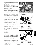
Page 112: ...own 2 Flange nut 3 Grooved pin 4 E ring 5 Groomer lift rod 6 Lock screw 7 Bushing 8 Lift arm assembly LH shown 9 Detent spring 10 Spring washer 11 Cap screw 12 Bushing 13 Wave washer 14 Groomer adjuster 13 3 5 14 2 6 4 7 12 9 10 8 11 7 1 Antiseize Lubricant Antiseize Lubricant Antiseize Lubricant ...

Page 113: ... lock screw item 6 to lift arm assembly Assembly Fig 17 1 Apply antiseize lubricant to threads of groomer lift rod item 5 and lift arm assembly item 8 Assemble groomer arm using Figure 17 as a guide 2 Install groomer arm onto cutting unit Fig 18 A Slide groomer arm onto front roller shaft and to cutting unit B Secure groomer arm to cutting unit side plate with HOC washer and lock nut C Secure groo...

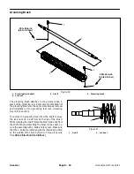
Page 114: ... procedure as removal and installation of the grooming reel see Grooming Reel in this section To remove the grooming brush from the shaft remove the lock nut and J bolt from both ends of the brush While retaining the shaft rotate the brush and slide from the shaft When assembling the brush to the shaft se cure the assembly with J bolts and lock nuts Make sure that the J bolts are installed with th...

Reviews: