Greensmaster Flex 18/21
Traction and Reel Drive System
Page 4 – 17
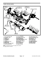
11. Slide gearbox assembly to the right side of mower,
away from the engine. This should allow the left gearbox
axle to clear the frame and the gearbox to separate from
the engine gear. Rotate and pivot gearbox assembly
and then slide right side axle from frame to complete
gearbox removal.
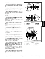
12.Slide bearings and bearing flangettes from gearbox
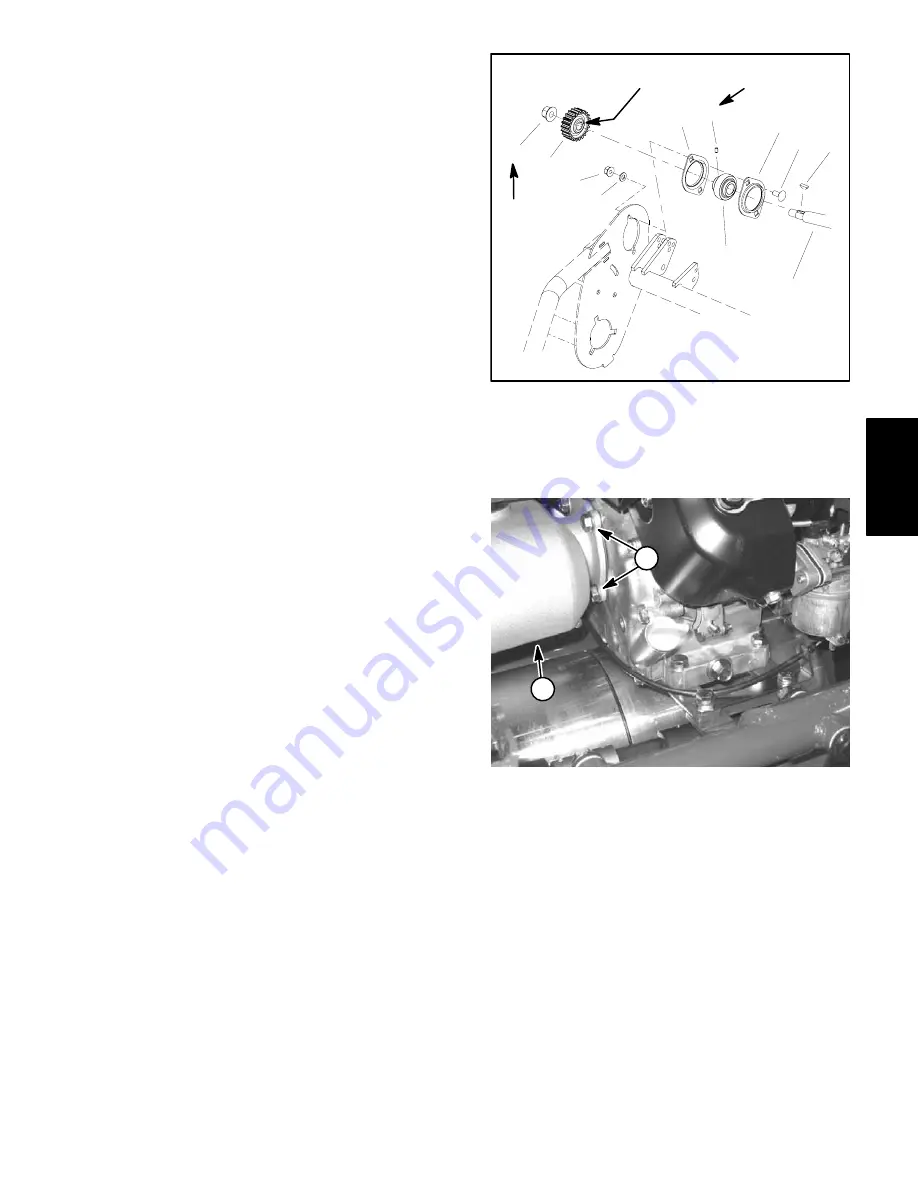
axle shafts.
13.Remove and discard flange gasket from between
engine and gearbox.
Gearbox Installation
1. Park traction unit on a level surface. Make sure en-
gine is OFF. Remove spark plug wire from the spark
plug.
2. Place new flange gasket on four (4) set screws
installed in engine mounting flange.
3. Slide bearings and bearing flangettes onto gearbox
axles. Make sure that extended race of bearings is posi-
tioned toward ends of axles.
4. Insert gearbox short axle through frame on right side
of mower. By rotating the gearbox, position left axle into
frame and input flange of gearbox to engine.
5. Install parking brake lever (with cable attached) to
brake shaft of gearbox noting location of alignment
splines on shaft and lever.
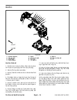
6. Rotate engine crankshaft slowly with recoil starter to
align crankshaft gear with gearbox input gear. Align
gearbox flange onto set screws. Install and tighten four
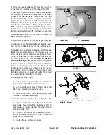
(4) flange nuts to secure gearbox to engine (Fig 20).
7. Secure extended race bearings and bearing flan-
gettes to frame with carriage bolts, flat washers and
flange nuts.
8. Check bearing alignment by rotating the long gear-
box axle shaft. Shaft should rotate easily if alignment is
correct.
9. Tighten the bearing set screws to secure the bear-
ings to the gearbox axles. Torque set screws from 40 to
50 in–lb (4.5 to 5.7 N–m).
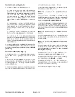
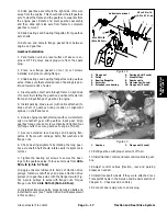
10.Apply antiseize lubricant to bores of traction drive
pulleys. Install woodruff keys and place traction drive
pulleys onto gearbox axles with the flange inward (Fig.
19). Secure pulleys to axles with flange nuts. Torque
flange nuts from 40 to 50 ft–lb (54 to 68 N–m).
11. Install traction drive belts, properly tension belts and
install belt covers (see Traction Drive Belt Replacement
in this section).
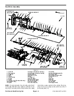
1. Flange
nut
2. Pulley
3. Bearing
flangette
4. Set
screw
5. Extended race bearing
6. Carriage bolt (2 used)
7. Woodruff
key
8. Gearbox
axle
9. Flat washer (2 used)
10. Flange nut (2 used)
Figure 19
6
2
1
5
3
3
7
8
9
4
Antiseize Lubricant
40 to 50 ft–lb
(54 to 68 N–m)
10
40 to 50 in–lb
(4.5 to 5.7 N–m)
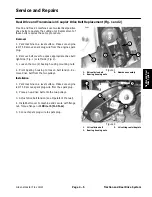
1. Gearbox
2. Flange nut (4 used)
Figure 20
1
2
12.Refill gearbox with proper amount of fluid.
13.Install traction control and reel control cables to gear-
box.
14.Adjust control cables (traction, reel and parking
brake) as needed.
15.Install transport wheels if they were attached (see
Transport Wheels in the Service and Repairs section of
Chapter 6 – Chassis and Controls).
16.Connect spark plug wire to spark plug.
Traction and Reel
Drive System
Summary of Contents for 04022 Greensmaster Flex 21
Page 2: ...Greensmaster Flex 18 21 This page is intentionally blank ...
Page 4: ...Greensmaster Flex 18 21 This page is intentionally blank ...
Page 58: ...Greensmaster Flex 18 21 Page 5 10 Electrical System This page is intentionally blank ...
Page 83: ...Greensmaster Flex 18 21 Page 7 13 Cutting Unit This page is intentionally blank Cutting Unit ...
Page 85: ...Greensmaster Flex 18 21 Page 7 15 Cutting Unit This page is intentionally blank Cutting Unit ...
Page 111: ...Greensmaster Flex 18 21 Groomer Page 8 15 This page is intentionally blank Groomer ...

