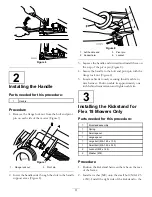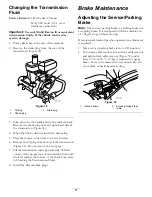
frame with the bolt and washer, the small spacer,
and locknut (M8–1.25) (Figure 9). Ensure the bolt
is installed from the inside of the frame as shown
in Figure 9.
3. Install a washer (M8) onto the large bolt (M8–1.25 x
100).
4. Install the spacer into the spring and install the large
bolt (M8–1.25 x 100) into the spacer.
Important:
When installing the spring, place
one end of the spring under the rear frame
(Figure 9).
5. Install the left side of the kickstand to the frame
with the bolt and washer, the large spacer and spring,
and locknut (M8–1.25) (Figure 9). Ensure the bolt
is installed from the inside of the frame as shown
in Figure 9.
Figure 9
1.
Left handle end
5.
Large bolt (M8–1.25 x
100)
2.
Locknut (M8–1.25)
6.
Spring
3.
Small spacer
7.
Large spacer
4.
Washer (M8)
8.
Ssmall bolt (M8–1.25 x
030)
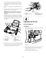
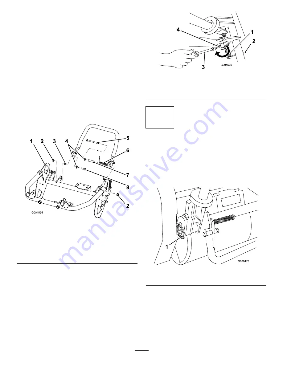
6. Place a nut runner over the end of the spring pointing
towards the rear and move the end of the spring over
and under the kickstand spacer (Figure 10).
Figure 10
1.
Spring
3.
Nut runner
2.
Spring end under the
frame
4.
Move the spring end under
the kickstand spacer.
4
Adjusting the Handle
No Parts Required
Procedure
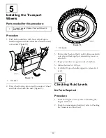
1. Remove hairpin cotters from ring pins on each side
of mower (Figure 11).
Figure 11
1.
Ring pins
2. While supporting handle, remove ring pins from
each side and raise or lower handle to desired
operating position (Figure 11).
3. Reinstall ring pins and hair pin cotters.
12


