background image

– change into neutral and set the parking brake;

– stop the engine.

Disengage drive to attachments when transporting
or not in use.

Stop the engine and disengage drive to attachment

– before refuelling;

– before removing the grass catcher/catchers;

– before making height adjustment unless

adjustment can be made from the operator’s
position.

– before clearing blockages;

– before checking, cleaning or working on the

mower;

– after striking a foreign object or if an abnormal

vibration occurs. Inspect the mower for damage
and make repairs before restarting and operating
the equipment.

Reduce the throttle setting before stopping engine
and, if the engine is provided with a fuel shut-off
valve, turn the valve off at the conclusion of mowing.

Keep hands and feet away from the cutting unit.

Slow down and use caution when making turns
and crossing roads and sidewalks. Stop reels if not
mowing.

Do not operate the mower under the influence of
alcohol or drugs

Lightning can cause severe injury or death. If
lightning is seen or thunder is heard in the area, do
not operate the machine; seek shelter.

Use care when loading or unloading the machine
into a trailer or truck

Use care when approaching blind corners, shrubs,
trees, or other objects that may obscure vision.

Maintenance and Storage

Keep all nuts, bolts and screws tight to be sure the
equipment is in safe working condition.

Never store the equipment with fuel in the tank
inside a building where fumes may reach an open
flame or spark.

Allow the engine to cool before storing in any
enclosure.

To reduce the fire hazard, keep the engine, silencer,
battery compartment and fuel storage area free of
grass, leaves, or excessive grease.

Check the grass catcher frequently for wear or
deterioration.

Keep all parts in good working condition and all
hardware and hydraulic fittings tightened. Replace all
worn or damaged parts and decals.

If the fuel tank has to be drained, do this outdoors.

Be careful during adjustment of the machine to
prevent entrapment of the fingers between moving
blades and fixed parts of the machine.

Disengage drives, disengage the cutting unit, set
parking brake, stop engine and disconnect spark plug
wire. Wait for all movement to stop before adjusting,
cleaning or repairing.

Clean grass and debris from cutting unit, drives,
mufflers, and engine to help prevent fires. Clean up
oil or fuel spillage.

Carefully release pressure from components with
stored energy.

Disconnect battery and remove spark plug wire
before making any repairs. Disconnect the negative
terminal first and the positive last. Reconnect
positive first and negative last.

Use care when checking the reel. Wear gloves and
use caution when servicing them.

Keep hands and feet away from moving parts. If
possible, do not make adjustments with the engine
running.

Toro Mower Safety

The following list contains safety information specific
to Toro products or other safety information that you
must know that is not included in the CEN, ISO, or
ANSI standard.

This product is capable of amputating hands and
feet and throwing objects. Always follow all safety
instructions to avoid serious injury or death.

Use of this product for purposes other than its intended
use could prove dangerous to user and bystanders.

Know how to stop the engine quickly.

Do not operate the machine while wearing tennis
shoes or sneakers.

Wearing safety shoes and long pants is advisable and
required by some local ordinances and insurance
regulations.

Handle gasoline carefully. Wipe up any spills.

Check the safety interlock switches daily for proper
operation. If a switch should fail, replace the switch
before operating the machine.

Always stand behind the handle when starting and
operating the machine.

5

Summary of Contents for 04025

Page 1: ...nd Mower Model No 04019 Serial No 311000001 and Up Model No 04024 Serial No 311000001 and Up Model No 04025 Serial No 311000001 and Up To register your product or download an Operator s Manual or Parts Catalog at no charge go to www Toro com Original Instructions EN ...

Page 2: ...refully to learn how to operate and maintain your product properly and to avoid injury and product damage You are responsible for operating the product properly and safely You may contact Toro directly at www Toro com for product and accessory information help finding a dealer or to register your product Whenever you need service genuine Toro parts or additional information contact an Authorized S...

Page 3: ...17 Think Safety First 17 Checking the Engine Oil Level 17 Filling the Fuel Tank 17 Checking the Interlock Switch Operation 18 Starting and Stopping the Engine 18 Transport Operation 18 Preparing to Mow 19 Mowing Operation 19 Maintenance 21 Recommended Maintenance Schedule s 21 Daily Maintenance Checklist 22 Engine Maintenance 23 Engine Oil 23 Servicing the Air Cleaner 24 Replacing the Spark Plug 2...

Page 4: ... following precautions Store fuel in containers specifically designed for this purpose Refuel outdoors only and do not smoke while refuelling Add fuel before starting the engine Never remove the cap of the fuel tank or add fuel while the engine is running or when the engine is hot If fuel is spilled do not attempt to start the engine but move the machine away from the area of spillage and avoid cr...

Page 5: ... good working condition and all hardware and hydraulic fittings tightened Replace all worn or damaged parts and decals If the fuel tank has to be drained do this outdoors Be careful during adjustment of the machine to prevent entrapment of the fingers between moving blades and fixed parts of the machine Disengage drives disengage the cutting unit set parking brake stop engine and disconnect spark ...

Page 6: ... Do not resume mowing until the area is cleared Maintenance and Storage Check all fuel lines for tightness and wear on a regular basis Tighten or repair them as needed If the engine must be running to perform a maintenance adjustment keep hands feet clothing and any parts of the body away from the cutting unit attachments and any moving parts Keep everyone away To ensure safety and accuracy have a...

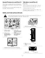
Page 7: ...36 Safety and Instructional Decals Safety decals and instructions are easily visible to the operator and are located near any area of potential danger Replace any decal that is damaged or lost 115 1613 1 Warning read the Operator s Manual 3 Thrown object hazard keep bystanders a safe distance from the machine 2 Warning remove the spark plug wire before performing any maintenance on the machine 4 C...

Page 8: ...ction drive 4 Forward 2 Reel drive 5 Lever engaged 3 Neutral 6 Lever disengaged 115 1614 1 Warning read the Operator s Manual 3 Thrown object hazard keep bystanders a safe distance from the machine 2 Warning do not operate the machine unless you are trained 4 Warning stay away from moving parts keep all guards in place 8 ...

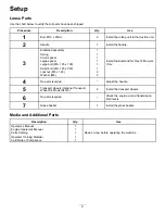
Page 9: ...ut M8 x 1 25 2 3 Washer M8 2 Install the kickstand for Flex 18 Mowers Only 4 No parts required Adjust the handle 5 Transport wheels Optional Transport Wheel Kit Model 04123 2 Install the transport wheels 6 No parts required Check the engine oil and transmission fluid levels 7 Grass basket 1 Install the grass basket Media and Additional Parts Description Qty Use Operator s Manual 1 Engine Operator ...

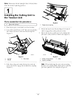
Page 10: ... 3 Kick stand 2 Handle 3 Push the cutting unit under the traction unit and then to the left to engage the transmission coupling Figure 4 Figure 4 1 Transmission coupling 4 Rotate the traction unit frame Figure 5 forward until it engages the cutting unit pivot arms 5 Secure the traction unit frame to the cutting unit pivot arms with 2 M10 x 25mm bolts Figure 5 Figure 5 1 Cutting unit pivot arms 3 B...

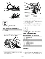
Page 11: ...8 4 Secure the handle to the bolt and pivot pin with the flange lock nut Figure 8 5 Locate cable tie loosely securing throttle cable to wire harness Position cable tie approximately one inch behind transmission and tighten cable tie 3 Installing the Kickstand for Flex 18 Mowers Only Parts needed for this procedure 1 Kickstand assembly 1 Spring 1 Small spacer 1 Large spacer 1 Large bolt M8 1 25 x 1...

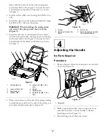
Page 12: ... the inside of the frame as shown in Figure 9 Figure 9 1 Left handle end 5 Large bolt M8 1 25 x 100 2 Locknut M8 1 25 6 Spring 3 Small spacer 7 Large spacer 4 Washer M8 8 Ssmall bolt M8 1 25 x 030 6 Place a nut runner over the end of the spring pointing towards the rear and move the end of the spring over and under the kickstand spacer Figure 10 Figure 10 1 Spring 3 Nut runner 2 Spring end under t...

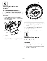
Page 13: ...el and slide wheel onto hex shaft Figure 13 Figure 13 1 Locking clip 3 Rotate wheel back and forth until it slides completely onto axle and locking clip is secured in groove on axle shaft 4 Repeat procedure on opposite side of machine 5 Inflate the tires to 12 15 psi 6 Carefully lift up on handle support to release kick stand 6 Checking Fluid Levels No Parts Required Procedure 1 Check the engine o...

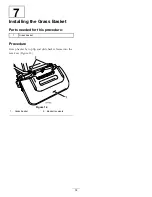
Page 14: ...stalling the Grass Basket Parts needed for this procedure 1 Grass basket Procedure Grasp basket by top lip and slide basket frame into the receivers Figure 14 Figure 14 1 Grass basket 2 Basket receivers 14 ...

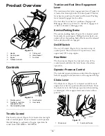
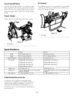
Page 15: ...ve top of lever to the left to engage reel or back to neutral to disengage reel Service Parking Brake The service parking brake Figure 16 is located on left front side of control panel Pulling the lever back over center will set the parking brake Brake must be released before traction drive is engaged On Off Switch The on off switch Figure 16 is located on top of control panel Move switch to On po...

Page 16: ... 8 cm 41 1 2 inches 105 4 cm Length with basket 61 1 2 inches 156 2 cm 61 inches 155 cm Model 04024 185 lb 84 kg Model 04019 175 lb 79 kg Model 04202 82 lb 37 kg Model 04206 82 lb 37 kg Model 04025 185 lb 84 kg Model 04207 89 lb 40 kg Net weight Model 04208 89 lb 40 kg Width of cut 21 inches 53 3 cm 18 inches 45 7 cm Height of cut 1 16 to 19 64 inches 1 5 to 7 5 mm with Micro Cut bedknife 1 16 to ...

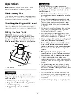
Page 17: ...that spills Do not fill the fuel tank completely full Add gasoline to the fuel tank until the level is 1 inch 25 mm below the bottom of the filler neck This empty space in the tank allows gasoline to expand Never smoke when handling gasoline and stay away from an open flame or where gasoline fumes may be ignited by a spark Store gasoline in an approved container and keep it out of the reach of chi...

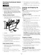
Page 18: ... and Stopping the Engine Note For illustrations and descriptions of the controls referenced in this section refer to the Controlws section in Operation Starting the Engine Note Make sure spark plug wire is installed on spark plug 1 Make sure traction and reel drive levers are in Disengaged position Note Engine will not start if traction lever is in the engaged position 2 Open the fuel shut off val...

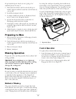
Page 19: ...the cutting unit Prior to Mowing Be sure the mower is carefully adjusted and is set evenly on both sides of the reel Improper mower adjustment is magnified in the appearance of the clipped turf Remove all foreign objects from turf prior to mowing Make sure everyone especially children and pets are clear of the work area Method of Mowing The greens should be mowed in a straight back and forth direc...

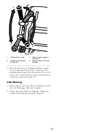
Page 20: ...ncrease throttle speed until the mower is traveling at the desired ground speed drive the mower out onto the green area lower the front of the mower down and commence operation Figure 23 After Mowing 1 Drive off green move reel drive and traction control levers to Disengage and stop the engine 2 Empty the grass catcher of clippings install grass catcher and commence transport operation 20 ...

Page 21: ...eck the engine oil level Every 25 hours Clean the air cleaner more often in dirty or dusty conditions Every 50 hours Change the engine oil Clean the fuel filter Check the transmission fluid level Every 100 hours Check the paper air filter element and replace as required more often in dirty or dusty conditions Check the spark plug Every 800 hours Change the transmission fluid Or 2 years whichever o...

Page 22: ...ng brake operation Check that pivot joints operate freely Check the fuel level Check the engine oil level Check the air filter Clean the engine cooling fins Check for unusual engine noises Check for unusual operating noises Check the reel to bedknife adjustment Check the height of cut adjustment Touch up damaged paint Notation for Areas of Concern Inspection performed by Item Date Information 22 ...

Page 23: ...utes before checking If the oil level is at or below the L mark on the dipstick add oil to bring the oil level to the H mark DO NOT OVERFILL If the oil level is between the H and L marks no oil addition is required 1 Remove the transport wheels if installed position the mower so the engine is level and clean around oil level gauge Figure 25 Figure 25 1 Oil level gauge 2 Drain plug 2 Remove oil lev...

Page 24: ...dry but do not twist because the foam may tear C Saturate element with clean engine oil Squeeze element to remove excess oil and to distribute oil thoroughly An oil damp element is desirable Figure 28 1 Foam element 2 Paper element 4 When servicing foam element check condition of paper element Replace as required Note Do not use compressed air to clean the paper element 5 Install foam element pape...

Page 25: ...tly gapped spark plug and tighten firmly to 17 ft lb 23 N m Figure 30 Fuel System Maintenance Cleaning the Fuel Filter Service Interval After the first 25 hours Every 50 hours 1 Close fuel shut off valve and unscrew bowl from filter body Figure 31 Figure 31 1 Shut off valve 2 Bowl 2 Clean bowl and filter in clean gasoline and install 25 ...

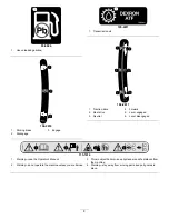
Page 26: ...sion Fluid Level Service Interval Every 50 hours The transmission is filled at the factory with approximately 94 fluid ounces of Mobil Dexron lll automatic transmission fluid Note The seals used in the transmission are internally lubricated with grease During initial operation of mower slight weeping of grease from these seals will occur Wipe off excess grease Important Use only Mobil Dexron lll o...

Page 27: ...on Figure 34 Do not remove the vent pipe 7 Fill the transmission with approximately 94 fluid ounces of the proper type of transmission fluid until the level reaches the bottom of the check hole refer to Checking the Transmission Fluid 8 Install the fill and check plugs Brake Maintenance Adjusting the Service Parking Brake Note The service parking brake is a holding brake not a stopping brake It is...

Page 28: ...to 5 16 inch 4 8 to 7 9 mm If the deflection is incorrect proceed to next step Figure 37 1 Reel drive belt 3 Driven pulley 2 Drive pulley 3 To adjust belt tension A Loosen the bearing housing mounting nuts Figure 38 Figure 38 1 Reel drive belt 2 Bearing housing mounting nuts B Using a 3 8 inch drive torque wrench rotate the bearing housing with 35 40 in lb 4 4 5 N m of torque to set belt tension F...

Page 29: ... proceed to next step Figure 41 1 Reel drive belt 3 To adjust belt tension A Loosen the bearing housing mounting nuts Figure 42 Figure 42 1 Reel drive belt 2 Bearing housing mounting nuts B Using a 3 8 inch drive torque wrench rotate the bearing housing with 35 40 in lb 4 4 5 N m of torque to set belt tension Figure 43 Figure 43 1 Bearing housing 2 3 8 Torque wrench here C While holding the torque...

Page 30: ... adjust belt tension A On back side of side plate loosen the bolt securing the idler bracket to the side plate Figure 46 Figure 46 1 Tang washer 2 Idler bracket bolt B Using a 3 8 inch drive torque wrench rotate the idler bracket with 35 40 in lb of torque to set the belt tension Figure 47 While holding the torque wrench setting tighten the idler bracket mounting bolt The tang washer is installed ...

Page 31: ...e jam nut 4 Check control operation Adjusting the Reel Control If reel control does not engage or it slips during operation an adjustment is required 1 Make sure traction control is properly adjusted refer to Adjusting the Traction Control 2 To increase cable tension loosen front cable jam nut and tighten back cable jam nut Figure 49 located on top of gear box until the reel cable force adds 7 to ...

Page 32: ...gine to distribute conditioned fuel through the fuel system 5 minutes B Either stop engine allow it to cool and drain the fuel tank or operate the engine until it stops C Restart the engine and run it until it stops Repeat on Choke until the engine will not restart D Dispose of fuel properly Recycle as per local codes Note Do not store stabilizer conditioned gasoline over 90 days 3 Check and tight...

Page 33: ...Notes 33 ...

Page 34: ...Notes 34 ...

Page 35: ...Notes 35 ...

Page 36: ...painted surfaces scratched decals or windows etc Parts Parts scheduled for replacement as required maintenance are warranted for the period of time up to the scheduled replacement time for that part Parts replaced under this warranty are covered for the duration of the original product warranty and become the property of Toro Toro will make the final decision whether to repair any existing part or...

Reviews: