G017235
1
2
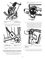
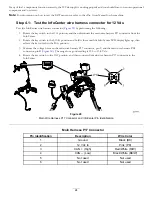
Figure 16
1.
Main wire harness P34
connector
2.
Li+ diagnostic wire
harness P34 connector
Secure the Battery Pack and Platform
1.
Remove the steel rod that is holding the battery
platform in the raised position, and gently lower the
battery platform to the machine frame (
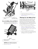
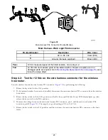
Figure 17
1.
Battery pack and platform
3.
Locking holes
2.
Pivot bolts and nuts
Important:
Do not pinch the wire harness
between the frame and the battery platform.
2.
Install the nut (
).
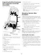
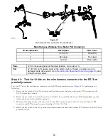
Figure 18
1.
Nut
3.
Tighten the pivot bolts and nuts (
).
4.
Connect the battery pack. Refer to
Battery Pack (page 17)
.
“Waking Up” the Battery Pack
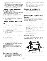
In normal operation, turning the key to the S
TART
position
“wakes up” the battery pack. This provides power to the
TEC-2401, which sends periodic “keep alive” messages
through the CAN bus to the battery controller to keep the
battery pack powered up. The Li+ diagnostic wire harness
allows the battery pack to power up momentarily so that you
can perform diagnostic procedures. The battery pack remains
on only momentarily because no CAN message is sent.
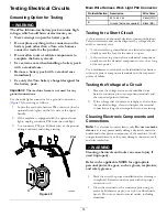
To “wake up” the battery pack, perform the following steps:
1.
Install the Li+ diagnostic wire harness. Refer to
Installing the Li+ Diagnostic Wire Harness (page 8)
.
2.
Disconnect the P06 and P07 connectors from P05 (the
molded storage cap).
3.
Connect the P06 and P07 connectors together.
4.
Listen for an audible “clunk” from the battery internal
contactor. For the next 2 to 3 seconds, the battery pack
will supply power to its output terminals.
12


