Appendix B:
Toro Electronic Controller Connections
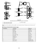
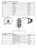
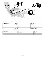
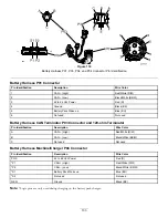
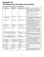
TEC-2401 Harness Connector P01 and P02 Pin Detail
Pin
Pin type
Wire color
Description
Detail
P1-1
Input, voltage
Blue (BU)
Key Start, Momentary
When the key switch is moved to the S
TART
position, this input to the TEC and battery pack
goes to ground and turns on the electronics.
When the key switch is moved to the O
FF
or R
UN
positions, this input is 42 to 64 Vdc.
Note:
For best starting results: When
InfoCenter red light turns on, release the
key. When connected to Toro DIAG, wait 2
seconds before releasing the key.
P1-2
Input Ground
(harness)
Violet (VIO)
Key Run
This input is grounded with key switch in the S
TART
or R
UN
position. It is 12 Vdc when the key switch
is in the O
FF
position. The TEC signals the battery
pack to Stay/Keep Alive.
P1-3
Output
Brown (BN)
Pre-Charge, Sense
This output slowly brings up the power to the
motor when the machine is turned on. It also
slowly discharges the power when the key switch
is moved to the O
FF
position. Pre-charge motor
side; sense for high and low voltage; initiate and
supply charge or discharge then charge.
P1-4
Output
Yellow (Y)
5 Vdc supply
5 Vdc supply for speed knob (potentiometer).
P1-5
Output
Pink (PK)
12 Vdc supply
12 Vdc supply for InfoCenter, hour meter (optional),
and slow-in-turn proximity sensor.
P1-6
Input, voltage
Tan (T)
Pre-Charge, Charge
Battery power to the TEC is turned on when
the key switch is in the R
UN
position. Required
to power up the motor; supplies circuit voltage
output through pin P1-3 until battery pack power
or greater motor capacitor charge is established.
P1-7
Input, digital high/low
Not used
Not used
Not used
P1-8
Input, digital high/low
Orange (OR)
Park Brake Prox SW NO
12 Vdc potential when the key switch is in the R
UN
position, waiting for flag to close proximity sensor.
12 Vdc Low state indicates digital Off/Inactive.
P1-9
Input, digital high/low
Not used
Not used
Not used
P1-10
Input, digital high/low
White (W)
Reel Prox SW NO
12 Vdc potential when the key switch is in the R
UN
position, waiting for flag to close proximity sensor.
12 Vdc Low state indicates digital On/Active.
P1-11
CAN BUS
Red/White (R/W)
CAN+ High
CAN High pin for CAN communications.
P1-12
CAN BUS
Black/White (BK/W)
CAN– Low
CAN Low pin for CAN communications.
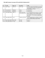
P2-1
Output, current
sinking
Violet (VIO)
Voltage for the main
contactor coil
42 to 64 Vdc when the key switch is in the R
UN
position; provides ground on successful pre-charge
sequence, closing the primary contactor contacts.
P2-2
Output
Not used
Not used
Not used
P2-3
Output
Not used
Not used
Not used
P2-4
Output
Not used
Not used
Not used
P2-5
Input Analog Variable
voltage
Blue (BU)
Analog In
Voltage of 0 to 5 volts from speed potentiometer;
speed knob rotated full backward = 0 to 1 volt
Speed knob rotated full forward = 4 to 5 volts
135

