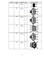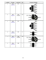
Step 4.1:
Check for 5 Vdc to the speed-control position sensor
potentiometer.
Perform the following steps with a multimeter, or use the InfoCenter Diagnostic display; refer to
Screen Icons (page 16)
.
1.
Rotate the key switch to the O
FF
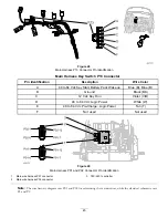
position, and then disconnect the main wire harness connector P05 (
at the speed-control position sensor potentiometer.
2.
Rotate the key switch to the S
TART
position and hold it there until the InfoCenter LCD display lights up, then
release the key switch to the R
UN
position.
3.
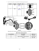
Measure the voltage between the main wire harness connector P05, pin C, and the main wire harness P04
connector, pin B (
). The normal voltage range is 4.91 to 5.09 Vdc.
4.
Rotate the key switch to the O
FF
position, and then connect the main wire harness P05 connector at the
speed-control position sensor potentiometer.
1
2
3
4
5
6
7
8
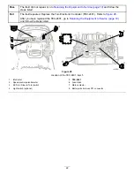
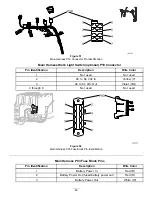
g030800
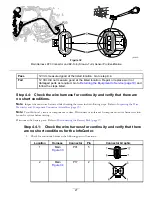
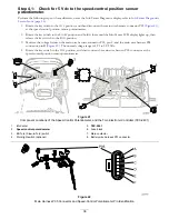
Figure 41
Component Locations of the Speed-Control Potentiometer, and the Toro Electronic Controller (TEC-2401)
1.
InfoCenter
5.
TEC-2401
2.
Speed-control potentiometer
6.
Fuse block
3.
EZ-Turn (Slow-in-Turn) switch
7.
Main contactor
4.
Work light switch (optional)
8.
Battery wire harness P01 connector
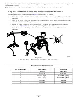
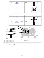
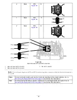
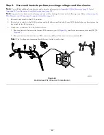
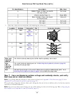
Figure 42
Main Harness P05 Connector and Speed-Control Potentiometer Pin Identification
36

