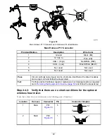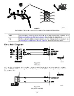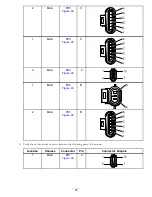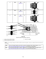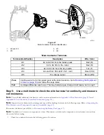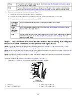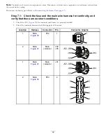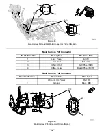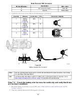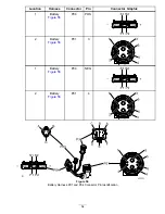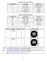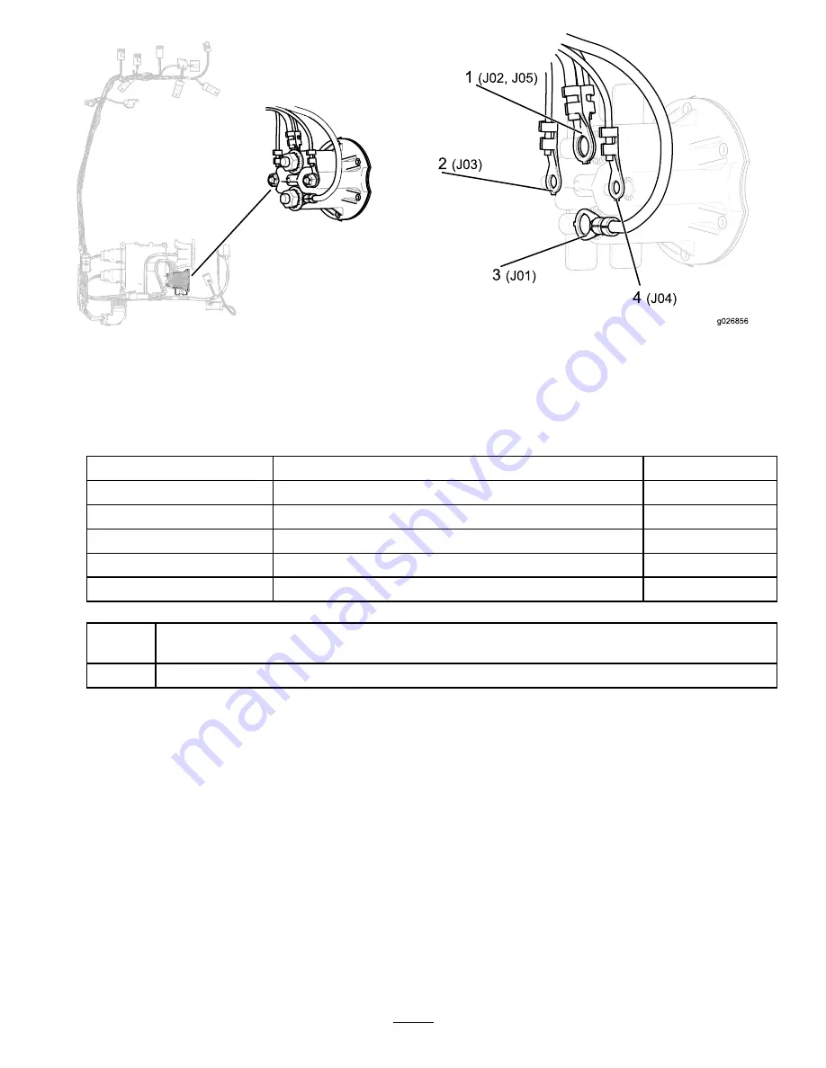
Figure 47
Main Contactor Terminal Identification
1.
J02 and J05
3.
J01
2.
J03
4.
J04
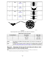
Main Contactor Terminals
Terminal Identification
Description
Wire Color
J01
42 to 64 Vdc from the battery pack
Red (R)
J02
42 to 64 Vdc to the motor
Red (R)
J03
42 to 64 Vdc from the key switch
Tan (T)
J04
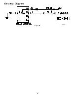
Ground from TEC-2401 P2-1 (coil)
Violet (VIO)
J05
Pre-charge sense
Brown (BN)
Pass
Continuous 42 to 64 Vdc tested good at the listed locations. Go to
to Service (page 19)
and follow the steps listed.
Fail
A voltage difference was found. This may indicate a pre-charge circuit failure. Go to step 5.
Step 5:
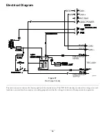
Use a multimeter to check the wire harness for continuity, and measure
coil resistance.
Note:
You will find additional wire harness and connector information in
Appendix A: Wire Harnesses (page 113)
and
Appendix B: Toro Electronic Controller Connections (page 135)
.
Note:
Inspect the wire harnesses for damage and wear while checking the items in the following steps. Refer to
Wire Harnesses and Component Connector Assemblies (page 13)
.
Disconnect the battery pack. Refer to
Disconnecting the Battery Pack (page 17)
.
Note:
Troubleshoot 1 circuit or component at a time. Disconnect or isolate each component or wire harness section from
the system before testing.
1.
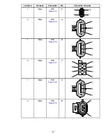
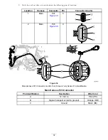
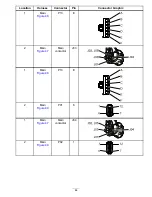
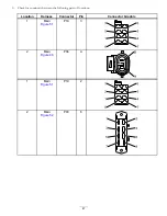
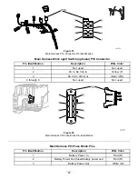
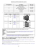
Check for continuity between the following pairs of locations:
43

