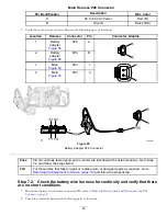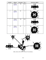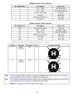
Fault 04 Pre-Charge
InfoCenter Display:
Battery Bus Fault
Fault Description
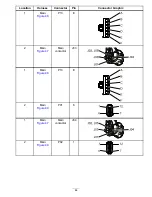
The battery pack voltage is too low for the machine to operate, or the voltage at main wire harness P01 connector, pin
3, failed to rise during pre-charge.
Circuit Description
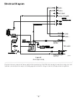
The main contactor connects the battery pack and the electric motor. The TEC-2401 circuitry monitors the voltage at several
locations to ensure the contactor is working properly and the voltage is correct to all components for operation.
Conditions for Setting the Fault
The TEC-2401 checks and then monitors for proper voltage. If the battery pack voltage is not reaching the minimum 33
Vdc, the system will trigger the fault.
The TEC-2401 confirms that the contactor voltage drops sufficiently during the discharge process and rises sufficiently during
the pre-charge process. Failure of either process will trigger a fault.
Recommended Service Actions
Step 1:
Verify that the fault repeats.
Note:
Turn off the optional work lights if installed, as they can cause initial excess circuit load and prevent the pre-charge
process from succeeding within the specified time.
1.
Clear the InfoCenter fault log. Refer to
Clearing the InfoCenter Fault Log (page 19)
.
2.
Disconnect the battery pack for 30 seconds. Refer to
Disconnecting the Battery Pack (page 17)
.
3.
Connect the battery pack. Refer to
Connecting the Battery Pack (page 17)
.
4.
Start and operate the machine. Refer to the
eFlex Operator’s Manual.
Pass
The fault did not repeat. Go to
Returning the Equipment to Service (page 19)
and follow the
steps listed.
Note:
If the fault does not repeat, a false detect event may have occurred.
Fail
The fault repeated. Go to step 2.
Step 2:
Charge the battery pack
Use the battery pack charger and charge the battery pack.
Note:
Refer to the Lithium Battery Pack Charger Operation section as found in the
eFlex Service Manual
Chapter 4, Electrical
System.
Pass
The fault did not repeat. Go to
Returning the Equipment to Service (page 19)
and follow the
steps listed.
Fail
The fault repeated. Go to step 3.
Step 3:
Remove 2 access covers to aid troubleshooting.
Performing these steps provides access to connectors on the wire harnesses.
1.
Remove the console cover. Refer to
Console Cover (page 19)
.
2.
Remove the power center cover. Refer to
Power Center Cover (page 20)
.
41

