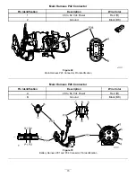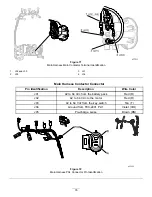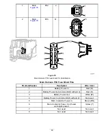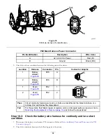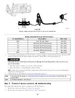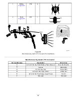
P01 Battery Harness Li+ Connector
Pin Identification
Description
Wire Color
1
CAN + (High)
Red/White (R/W)
2
CAN – (Low)
Black/White (BK/W)
3
42 to 64 Vdc Power
Red (R)
4
Ground
Black (BK)
5
Battery Pack Wake Up
Blue (BU)
6
Not used
Not used
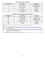
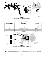
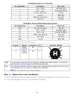
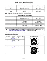
P04 Battery Harness Machine/Charger Connector
Pin Identification
Description
Wire Color
POS
42 to 64 Vdc Power
Red (R)
P1
CAN + (High)
Red/White (R/W)
P2
CAN – (Low)
Black/White (BK/W)
S1
Battery Pack Wake Up
Blue (BU)
S2
Not used
Not used
NEG
Ground
Black (BK)
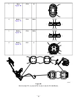
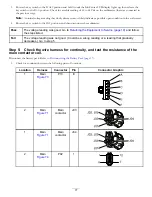
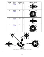
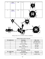
3.
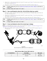
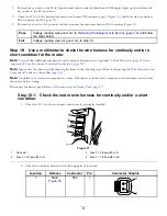
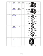
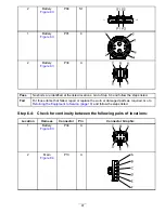
Check for a short between the following pins:
Location
Harness
Connector
Pin
Connector Graphic
1
Battery
P01
3
2
Battery
P01
4
1
2
3
5
6
4
Pass
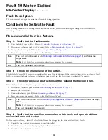
Circuit continuity tested good and no shorts are identified at the listed locations. Go to
the Equipment to Service (page 19)
and follow the steps listed.
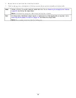
Fail
For those items that failed, repair or replace worn or damaged parts as required. Go to
the Equipment to Service (page 19)
and follow the steps listed.
Note:
Do not replace the motor unless the fault repeats.
Step 11:
Replace the motor (conditional).
If Steps 10.1 and 10.2 passed, and Fault 9 repeated immediately after returning the equipment to service, then replace the motor.
Go to
Returning the Equipment to Service (page 19)
and follow the steps listed.
86

