1.
Move the service/park brake lever to the OFF
position.
2.
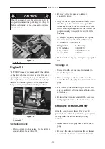
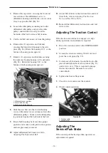
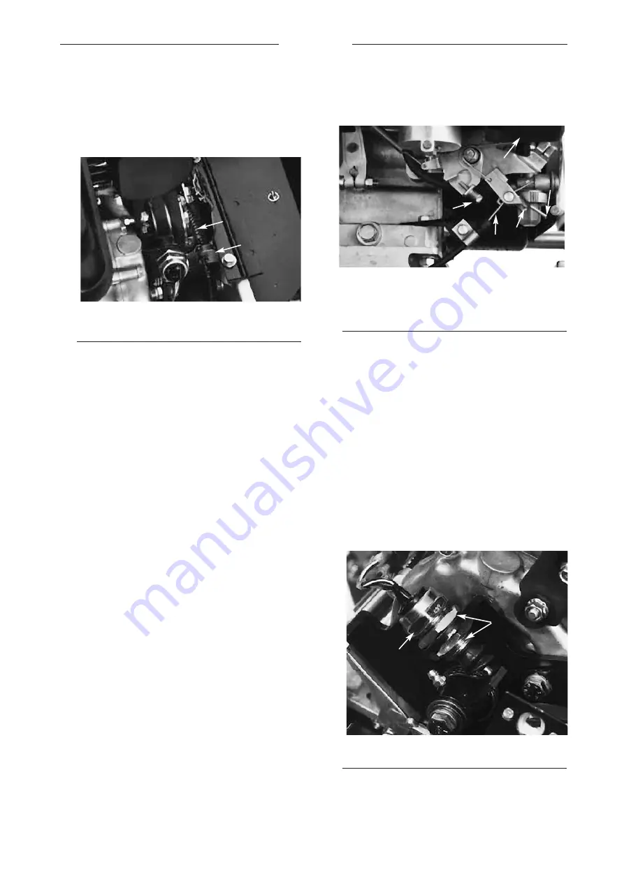
Loosen the retainer securing the v-belt cover
and pivot the cover open (Fig. 36).
Figure 36
1. Service/park brake cable
2. Front jam nut
3.
To increase cable tension, loosen the front cable
jam nut and tighten back the cable jam nut
(Fig. 35) until a force of 4–7 Nm. is required to
engage the brake. Measure force at the lever
knob. Do not
over
adjust, so brake band drags.
4. Close cover and secure the retainer.
Adjusting The Throttle Control
If a new throttle cable must be installed or the cable
becomes mis-adjusted, adjust as follows:
1.
Move the throttle control to the SLOW position.
2.
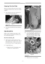
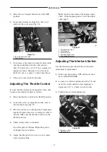
Loosen the screw securing the throttle cable to
the carburetor arm (Fig 37).
3.
The arm will move to idle position if improperly
adjusted. Tighten the screw securing the cable to
the arm. Make sure the throttle control is in the
SLOW position.
4.
Check setting with a tachometer.
Low idle speed is 800 rpm. High idle speed is
1800 rpm (See note below)
5.
Adjust the idle speed screws in or out to attain
correct speed setting.
Note:
Speed is measured at the engine output
shaft. Actual engine speed is twice the output
shaft speed.
Figure 37
1. Throttle cable screw
2. Throttle cable
3. Carburetor arm
4. Low speed idle screw
5. High speed idle screw
Adjusting The Interlock Switch
Use the following procedure if the switch needs
adjustment or replacement.
1.
Make sure the engine is OFF and the traction
lever is DISENGAGED.
2.
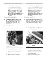
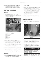
Loosen (2) switch mounting nuts (Fig. 38) and
move the switch until the switch plunger is
depressed .4.57 ± .1.5mm (switch closed).
3.
Tighten the switch mounting nuts.
Figure 38
1. Interlock switch
2. Mounting nuts
– 27 –
Maintenance
1
1
1
2
2
3
4
5
2
Summary of Contents for 04052TE
Page 16: ...Fig 16 1 Recoil starter 2 On Off switch 3 Kickstand Controls 16 3 2 1 ...
Page 30: ......
Page 31: ......
Page 32: ......

