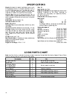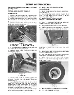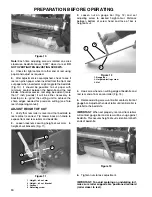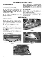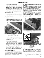
. Rotate belt guide clockwise until a gap of
approximately .06" is obtained between guide
finger and backside of drive belts.
. Tighten capscrew and lock nut securing idler
pulley and belt guide to idler arm. The .06"
dimension is a starting recommendation the actual
gap may vary per machine.
Close cover and secure retainer.
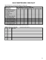
Remove capscrews securing traction drive and
reel drive belt covers to right side plate and remove belt
covers.
Loosen idler pulley mounting nut, on each idler
pulley and pivot each idler pulley counterclockwise
away from the backside of each belt to release belt
tension. Remove belts.
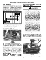
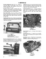
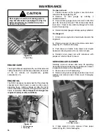
Remove capscrews securing front and rear
sections of differential cover to differential housing and
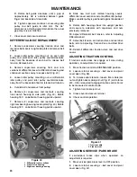
slide cover sections away to expose belt (Fig. 40).
Loosen idler pulley mounting nut, on differential
idler pulley and pivot idler pulley counterclockwise
away from the backside of belt to release belt tension.
Cut old belt and remove from pulleys.
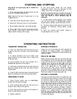
Remove (2) capscrews and locknuts securing
front clutch housing to side plate (Fig. 40). Rotate
housing 180
_
, so bottom of housing points upward.
Remove (2) capscrews and locknuts securing
right rear bearing housing to side plate (Fig. 40). Rotate
housing 180
_
, so bottom of housing points upward.
)'2/%
)&&%/%-1)"+ $.3%/ 0%$1).-0
/.-1 $+21$( (.20)-'
)'(1 /%"/ #%"/)-' (.20)-'
Slide new belt over rotated housing covers,
differential cover sections and onto differential pulleys.
Make sure idler pulley is positioned against backside of
belt.
Rotate both housings back into upright position
and secure to sideplate with capscrews and nuts
previously removed.
Adjust differential belt tension, refer to Adjusting
Differential belt.
Adjust belt tension on traction drive and reel drive
belts, refer to Adjusting Traction Drive and Reel Drive
belts.
Reinstall differential, traction drive and reel drive
covers.
If traction control does not engage or it slips during
operation, an adjustment is required.
Move traction control to DISENGAGED position.
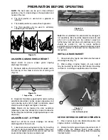
Loosen retainer securing v-belt cover and pivot
cover open (Fig. 38).
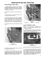
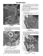
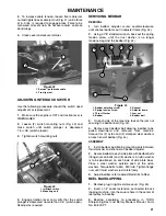
To increase cable tension, loosen front cable jam
nut and tighten back cable jam nut (Fig. 41) until a force
of 3-5 lbs. is required to engage traction control. Force
to be measured at control knob.
Tighten front cable jam nut.
Close cover and secure retainer.
Check control operation.
)'2/%
/"$1).- $"#+%
/.-1 *", -21
!
If service/park brake slips when operated, an
adjustment is required.
Move service/park brake lever to OFF position.
Loosen retainer securing v-belt cover and pivot
cover open (Fig. 42).

