11
Installing the Handle
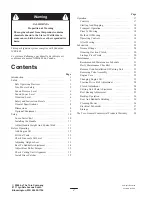
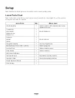
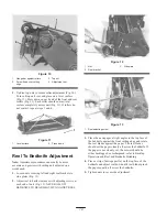
1. Remove handle mounting capscrew, washer and flange
lock nut from main fame (Fig. 1).
2. Secure handle and bell cranks to frame with capscrew,
washer nut previously removed (Fig. 1).
2
1
3
Figure 1
1.
Handle
2.
Bellcrank–clutch
3.
Bellcrank–throttle
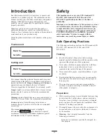
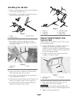
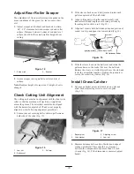
3. Raise handle assembly, fit adjusting bar through
slotted hole in handle and latch handle into notch in
adjusting bar (Fig. 2).
1
2
3
Figure 2
1.
Adjusting bar
2.
Notches
3.
Handle
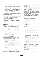
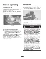
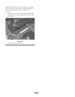
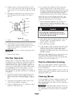
4. Secure clutch rod to center hole in clutch bell crank
with a flat washer and cotter pin (Fig. 3).
5. Insert throttle wire through small hole in throttle bell
crank and throttle stop (Fig. 3).
6. Secure throttle wire and throttle stop to bell crank with
throttle wire retainer, retainer screw and nut (Fig. 3).
7. Hook return spring into hole in engine bracket and
small hole in clutch bell crank (Fig. 3).
1
2
3
4
5
6
Figure 3
1.
Clutch rod
2.
Throttle wire
3.
Throttle stop
4.
Throttle wire retainer
5.
Return spring
6.
Engine bracket
Adjust Handle Height And
Control Bail
Adjust the height of the handle and travel of the control
bail for operator comfort.
1. To adjust handle height. grasp handle, push down on
adjusting bar with your foot and move handle
assembly up or down until most comfortable position
is achieved (Fig. 2). Lift foot and allow handle to lock
into notch in adjusting handle.
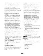
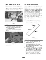
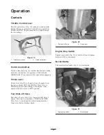
2. To adjust control bail travel, loosen nuts securing
turnbuckle to clutch rod (Fig. 4).
1
2
3
Figure 4
1.
Clutch control bail
2.
Control rod
3.
Turnbuckle
3. Rotate turnbuckle until traction wheels spin, on a
cement floor, when clutch is engaged.
Important
Mower should remain stationary when
engine is running and clutch is in the disengaged position.
4. Tighten nuts securing turnbuckle.


