background image

14

2

1

4

3

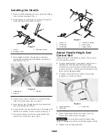
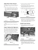
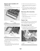
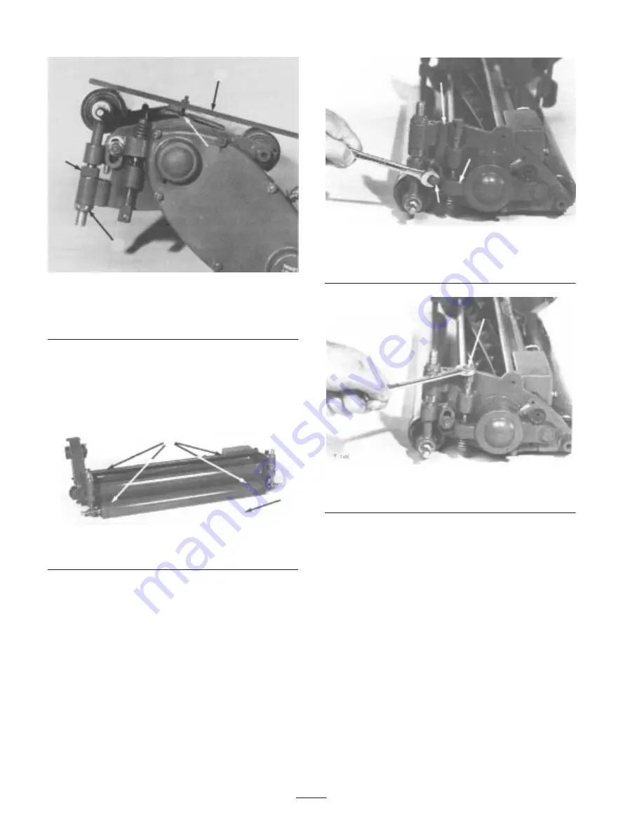
Figure 10

1.

Gauge bar against rollers

2.

Screw head over cutting
edge

3.

Top nut

4.

Adjustment nut

5. Tighten top nuts to secure roller adjustment (Fig. 10).

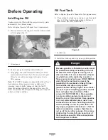
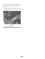
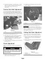
Turn cutting unit over and place on a level surface
(Fig. 11). Press down on each end of the front and rear
rollers (Fig. 11). Each roller should contact level
surface completely across unit (Fig. 11). If rollers do
not contact, repeat steps 3 and 4.

2

1

Figure 11

1.

Level surface

2.

Press down

Reel To Bedknife Adjustment

Note: Adjustment procedures can usually be more
accurate and precise with cutting unit adjusted on a
workbench.

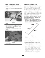
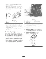
1. Loosen nuts securing left and right reel brackets to

side plates (Fig. 12).

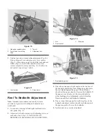
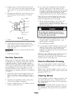
2. Adjust reel to knife clearance with adjusting screws at

each end of unit (Fig. 13). NEVER ALLOW
BEDKNIFE TO BEAR HEAVILY AGAINST REEL.

2

1

3

Figure 12

1.

Nut

2.

Reel bracket

3.

Side plate

1

Figure 13

1.

Reel adjusting screw

3. Place the newspaper at right angles to the top face of

the bedknife against the front cutting edge and rotate
the reel blades against the paper. The reel blades
should cut the paper cleanly all across the bedknife. If
the paper is not cleanly cut, the mower should be
either backlapped or resharpened: refer to Backlap
Operation and Reel and Bedknife Grinding.

4. Place a strip of newspaper flat on the top face of the

bedknife and adjust reel down until reel blades pinch
the paper equally all across the bedknife.

5. Tighten nuts to secure the adjustment.

Summary of Contents for 04130 Greensmaster 500

Page 1: ...Operator s Manual Domestic English EN Form No 3350 271 Greensmaster 500 Greensmaster Walk Behind Mower Model No 04130 250000001 and Up Traction Unit Model No 04215 250000001 and Up Cutting Unit ...

Page 2: ...dle Height And Control Bail 11 Before Operating 12 Add Engine Oil 12 Fill Fuel Tank 12 Check Transaxle Oil Level 13 Adjusting Height of cut 13 Reel To Bedknife Adjustment 14 Adjust Rear Roller Scraper 15 Check Cutting Unit Alignment 15 Install Grass Catcher 15 Page Operation 17 Controls 17 Starting And Stopping 18 Transport Operation 18 Prior To Mowing 18 Method Of Mowing 18 Operating Controls 18 ...

Page 3: ...1997 ISO standard 5395 1990 and ANSI B71 4 1999 specifications in effect at the time of production Improper use or maintenance by the operator or owner can result in injury To reduce the potential for injury comply with these safety instructions and always pay attention to the safety alert symbol which means CAUTION WARNING or DANGER personal safety instruction Failure to comply with the instructi...

Page 4: ... the face of the slope unless the mower is designed for this purpose Stay alert for holes in the terrain and other hidden hazards Watch out for traffic when crossing or near roadways Stop the blades rotating before crossing surfaces other than grass When using any attachments never direct discharge of material toward bystanders nor allow anyone near the machine while in operation Never operate the...

Page 5: ...he engine running Toro Mower Safety The following list contains safety information specific to Toro products or other safety information that you must know that is not included in the CEN ISO or ANSI standard This product is capable of amputating hands and feet and throwing objects Always follow all safety instructions to avoid serious injury or death Use of this product for purposes other than it...

Page 6: ... regular basis Tighten or repair them as needed If the engine must be running to perform a maintenance adjustment keep hands feet clothing and any parts of the body away from the cutting unit attachments and any moving parts especially the screen at the side of the engine Keep everyone away To ensure safety and accuracy have an Authorized Toro Distributor check the maximum engine speed with a tach...

Page 7: ...bottom of the filler neck 3 Thrown object hazard keep bystanders away 4 Cutting hazard to fingers hands and feet do not open or remove safety shields while engine is running Part No 93 9886 1 Use unleaded fuel only Part No 93 6688 1 Danger readthe operator s manual before performing maintenance 2 Cutting hazard to hands fingers and feet stop the engine before going near rotating reels Part No 95 7...

Page 8: ...on ball bearings Reduction Engine to Traction Drum 13 86 1 Traction Drive Clutch Friction Disk type Hand operated latch and bail at handle Differential Enclosed spur gears Handle 7 8 in diameter 17 gauge welded steel tubing with formed steel reinforcement panel Traction unit construction Cast aluminum housing Reel construction Cast aluminum and zinc side plates aluminum extrusion back plate Reel u...

Page 9: ...Kit Part No 2 2949 Skid Kit Part No 4 7299 Sectional Roller Part No 4 7319 Urethane Comb Part No 8 2560 Full Roller Part No 4 7309 Micro Cut Bedknife Part No 95 3147 Wiehle Roller rear cutting unit Part No 100 1556 Spark Arrester Kit Part No 98 3426 Low Cut Bedknife Part No 88 8990 ...

Page 10: ...n machine Mounting fasteners loosely installed on mower Throttle stop Wire retainer Retainer screw Retainer nut 1 1 1 1 Mount throttle wire Cotter pin Washer Spring 1 1 1 Mount clutch rod Gauge Bar Assembly 1 Use to set height of cut Machine Screw 10 32 x 0 88 in 22 mm 1 Install in gauge bar Jam Nut 10 32 1 Install on machine screw Grass Basket 1 Install on machine EEC Noise Certification 1 Operat...

Page 11: ...k return spring into hole in engine bracket and small hole in clutch bell crank Fig 3 1 2 3 4 5 6 Figure 3 1 Clutch rod 2 Throttle wire 3 Throttle stop 4 Throttle wire retainer 5 Return spring 6 Engine bracket Adjust Handle Height And Control Bail Adjust the height of the handle and travel of the control bail for operator comfort 1 To adjust handle height grasp handle push down on adjusting bar wi...

Page 12: ...o higher than to bottom of filter screen DO NOT OVER FILL 1 Figure 6 1 Fuel tank cap 2 Install fuel tank cap and wipe up any spilled gasoline Danger Because gasoline is flammable caution must be used when storing or handling it Do not fill fuel tank while engine is running hot or when machine is in an enclosed area Vapors may build up and be ignited by a spark or flame source many feet away DO NO ...

Page 13: ...gressively lower heights of cut with the same gauge setting may be obtained by selecting in the following order the skid full front roller sectional roller or the Wiehle roller The reason for this is that progressively less supporting or contact area is provided for the cutting unit The micro cut bedknife provides a height of cut to 1 16 if desired 1 Loosen nut on gauge bar and set adjusting screw...

Page 14: ...d right reel brackets to side plates Fig 12 2 Adjust reel to knife clearance with adjusting screws at each end of unit Fig 13 NEVER ALLOW BEDKNIFE TO BEAR HEAVILY AGAINST REEL 2 1 3 Figure 12 1 Nut 2 Reel bracket 3 Side plate 1 Figure 13 1 Reel adjusting screw 3 Place the newspaper at right angles to the top face of the bedknife against the front cutting edge and rotate the reel blades against the...

Page 15: ...e yoke Fig 15 1 3 2 Figure 15 1 Jam nut 2 Ball socket 3 Pull arm 2 Slide sleeves back on each ball joint and rotate each pull arm upward off the ball studs 3 Align cutting unit with roller and driveshaft with transaxle shaft and lengthen or shorten pull rods by threading ball socket on rod Fig 15 4 Align ball sockets with ball studs so hooded portion of socket is at top and open side toward stud F...

Page 16: ...nto basket Adjust screw to lower basket Fig 17 Make sure basket clears roller by at least 1 16 in 1 6 mm 3 Tighten jam nuts on each side of basket for adjusting screws Fig 17 Be sure dimension is equal on both sides of unit 1 Figure 18 1 1 4 inch 6mm maximum clearance ...

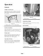
Page 17: ...ver Choke lever Fig 20 is located at rear of engine Lever has two positions RUN and CHOKE Move lever to CHOKE position when starting a cold engine After engine starts move lever to RUN position Fuel Shut off Valve Fuel shut off valve Fig 20 is located at right side of engine Valve has two positions CLOSED and OPEN Move lever to closed position when storing machine Open valve before starting engine...

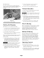
Page 18: ...l is DISENGAGED and start engine 2 Disengage cutting unit drive Fig 22 Important Excessive operating of the cutting unit with the absence of any grass clippings lubricant can damage the cutting unit 3 Place the handle assembly in the uppermost notch on handle adjusting bar Set throttle control in SLOW tip front of machine up and slowly increase engine speed while gradually engaging clutch control ...

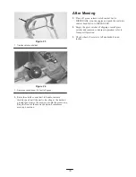
Page 19: ...rive the mower out onto the green area drop the front of the mower down and commence mowing operation After Mowing 1 Drive off green release clutch control bail to DISENGAGE stop the engine and push the reel drive control knob full in to DISENGAGE 2 Empty the grass catcher of clippings install grass catcher and commence transport operation refer to Transport Operation 3 Chock wheels if mower is le...

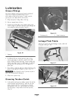
Page 20: ...ove fittings and replace pipe plugs Fig 25 Apply grease to enclosed bearing areas only until pressure is felt against the grease gun Front roller or support yoke pivot and pull arms apply grease to bearings until it begins to show Fig 25 Important Do not apply too much pressure or grease seals will be permanently damaged 3 Wipe excess grease away Greasing Traction Clutch 1 At the end of each seaso...

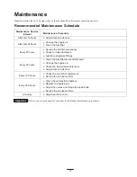
Page 21: ...cleaner Check for loose fasteners Lubricate all grease fittings Every 50 hours Clean the fuel filter and sediment bowl Change the engine oil Check the transmission fluid level Adjust traction belt drive Every 100 hours Check the cut off bar adjustment Service the air cleaner filter Every 200 hours Clean the combustion chamber Replace the spark plug Adjust the valves and torque the head bolts Servi...

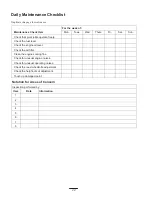
Page 22: ...rate freely Check the fuel level Check the engine oil level Check the air filter Clean the engine cooling fins Check for unusual engine noises Check for unusual operating noises Check the reel to bedknife adjustment Check the height of cut adjustment Touch up damaged paint Notation for Areas of Concern Inspection performed by Item Date Information 1 2 3 4 5 6 7 8 ...

Page 23: ... support hooks Fig 29 3 Align pull arms with ball studs slide sleeves back on sockets and drop arm sockets down on ball studs Fig 30 4 Make sure the cutting unit is aligned with the yoke roller and the drive shaft with the transaxle shaft If there is misalignment refer to Check Cutting Unit Alignment Removing Yoke Assembly To remove yoke 1 Remove grass catcher and unhook chains from support hooks ...

Page 24: ...and install belt guard Fig 32 Clutch Adjustment Should clutch slip during operation check and adjust as follows Do not adjust clutch with the engine running Clutch could catch and cause harm to both you and machine Warning 1 Tighten clutch locknut in small increments start engine and test adjustment Fig 33 2 Traction wheels will spin on a cement floor when clutch is engaged 1 2 Figure 33 1 Locknut...

Page 25: ...s a part of your troubleshooting procedures if your cutting unit performance has deteriorated Also check and adjust the reel bearings before doing any reel grinding 1 Remove grass catcher and cutting unit from traction unit refer to Removal and Installation of Cutting Unit 2 Remove locknut reel adjustment screw Allen head set screw and capscrew from left reel bracket Remove reel bracket from left ...

Page 26: ... should be mixed with liquid detergent soap until the material is of free flowing consistency Note Paste type pre mixed lapping compound is also sold in some areas This is generally used in its original composition and therefore is not free flowing 5 Operate the lapping machine so the reel turns in a reverse direction for about three minutes apply lapping solution continuously with a paint brush a...

Page 27: ... slowly to distribute oil on inside of cylinder Reinstall spark plug If torque wrench is not used tighten plug firmly DO NOT INSTALL WIRE ON SPARK PLUG Remove the belt cover over left side of machine Inspect the belt for excessive wear or damage Repair or replace as necessary Assure belt is in disengaged position Check condition of reel blades and bedknife repair and sharpen as necessary refer to ...

Page 28: ...t limited to weather storage practices contamination use of unapproved coolants lubricants additives or chemicals etc Normal wear and tear items Normal wear and tear includes but is not limited to damage to seats due to wear or abrasion worn painted surfaces scratched decals or windows etc Parts Parts scheduled for replacement as required maintenance are warranted for the period of time up to the ...

Reviews: