15
1
1
2
3
3
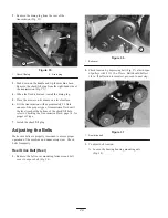
Figure 12
1.
Cutting unit pivot arms
2.
Traction unit frame tube
3.
Capscrews
5. Rotate pivot arms forward (Fig. 12) and rest traction
unit on restrained kickstand.
6. Pull cutting unit forward about 2 in. (51 mm) and then
to the right to disengage the transmission coupling
(Fig. 12).
1
Figure 13
1.
Transmission coupling
2.
7. Reverse procedure to install cutting unit.
Leveling the Rear Roller to the
Reel
1. Position cutting unit on a flat, level surface preferably
a precision ground surface plate.
2. Place a 1/4 in. (6.4 mm) or thicker plate under the reel
blades and against front edge of bedknife.
Note: Be sure the plate covers the full length of the reel
blades and three blades contact.
3. Firmly press down on cutting unit and maintain
pressure on rear roller. Try inserting a piece of paper
under each end of the roller. If the gap is greater than
the piece of paper, on either end, an adjustment may
be required, proceed to step 4.
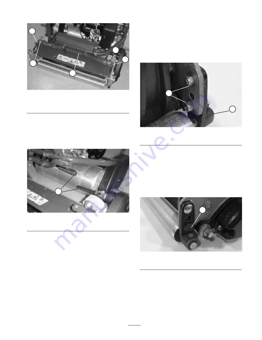
4. Loosen locknuts securing right rear roller bracket to
cutting unit sideplate (Fig. 14).
1
2
Figure 14
1.
Right rear roller bracket
2.
Locknuts
5. While holding reel securely on plate and maintaining
pressure on rear roller, rotate lower right roller
mounting bolt (Fig. 15). This mounting bolt has an
offset, which when rotated, acts as an eccentric (cam)
to raise or lower the roller. There is an I.D. dot which
denotes the offset of the bolt. Dot indicates in which
direction right end of roller moves when bolt is turned
and should always be in the rear half of the arc as
shown in figure 15.
1
Figure 15
1.
Eccentric bolt
Note: If additional adjustment is required, replace the
screw on the left-hand bracket with another eccentric bolt,
Part No. 105–3833. Ensure both rear roller brackets are in
the same hole.
6. To verify if roller is level, try inserting a piece of
paper under each end of roller.


