background image

16

7. When roller is level, tighten nuts securely.

Adjusting the Bedknife to the
Reel

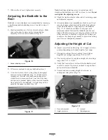
Bedknife to reel adjustment is accomplished by loosening
or tightening bedbar adjusting screws, located on top of
mower.

1. Position machine on a flat, level work surface. Make

sure reel contact is removed by turning bedbar
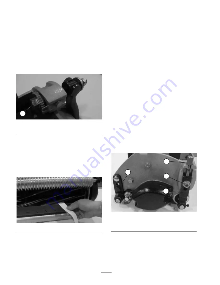
adjusting screws counterclockwise (Fig. 16).

1

Figure 16

1.

Bedbar adjusting screw

2. Tilt mower on back to expose bedknife and reel.

3. At one end of reel, insert a long strip of newspaper

between reel and bedknife (Fig. 17). While slowly
rotating reel forward, turn bedbar adjusting screw
clockwise (on same end of reel, one click at a time,
until paper is pinched lightly, when inserted from the
front, parallel to the bedknife. A slight drag will be
noted as the paper is pulled (Fig. 16).

Figure 17

Note: Each time adjusting screw is rotated one click
clockwise, bedknife moves .0007 in. closer to reel. Do not
overtighten the adjusting screws.

4. Check for light contact at other end of reel using paper

and adjust as required.

5. After adjustment is accomplished, check to see if reel

can pinch paper when inserted from the front and cut
paper when inserted at a right angle to the bedknife
(Fig. 17). It should be possible to cut paper with
minimum contact between the bedknife and the reel
blades. Should excessive reel drag be evident it will be
either necessary to backlap or regrind the cutting unit
to achieve the sharp edges needed for precision cutting
(see Toro reel sharpening manual).

Adjusting the Height of Cut

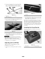
1. Adjust rear roller brackets (Fig. 18) to upper or lower

position depending on desired height of cut range.

The upper position (factory setting) is used when
height of cut settings range from 1/16 to 5/32”.

The lower position is used when height of cut settings
range from 1/8” to 19/64”.

2. Verify that rear roller is level and that bedknife to reel

contact is correct. Tip mower on back to expose front
and rear rollers and bedknife.

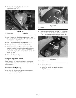
3. Loosen locknuts securing height-of-cut arms  to

cutting unit side plates (Fig. 18).

2

3

4

1

Figure 18

1.

Rear roller bracket

2.

Height-of-cut arm

3.

Locknut

4.

Adjusting screw

Summary of Contents for 04200

Page 1: ...perator s Manual Domestic English EN Form No 3327 369 Rev A Greensmaster Flex 21 Greensmaster Walk Behind Mower Model No 04021 210000001 and Up Traction Unit Model No 04200 210000001 and Up Cutting Unit ...

Page 2: ... Wheels 12 Before Operating 13 Adding Engine Oil 13 Filling the Fuel Tank 13 Checking the Transmission Fluid 14 Separating Cutting Unit from Traction Unit 14 Leveling the Rear Roller to the Reel 15 Adjusting the Bedknife to the Reel 16 Adjusting the Height of Cut 16 Adjusting the Cut Off Bar 17 Installing the Grass Basket 17 Checking the Interlock Switch Operation 18 Page Operation 18 Think Safety...

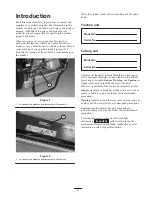
Page 3: ...e product model and serial numbers in the space below Traction unit Model No Serial No Cutting unit Model No Serial No This manual identifies potential hazards and has special safety messages that help you and others avoid personal injury and even death Danger Warning and Caution are signal words used to identify the level of hazard However regardless of the hazard be extremely careful Danger sign...

Page 4: ...wn by the machine Warning Fuel is highly flammable Take the following precautions Store fuel in containers specifically designed for this purpose Refuel outdoors only and do not smoke while refuelling Add fuel before starting the engine Never remove the cap of the fuel tank or add fuel while the engine is running or when the engine is hot If fuel is spilled do not attempt to start the engine but m...

Page 5: ...mowing Do not operate the mower under the influence of alcohol or drugs Use care when loading or unloading the machine into a trailer or truck Use care when approaching blind corners shrubs trees or other objects that may obscure vision Maintenance and Storage Keep all nuts bolts and screws tight to be sure the equipment is in safe working condition Never store the equipment with fuel in the tank ...

Page 6: ...engine L Remove transport wheels M Start engine N Engage reel drive Using the machine demands attention To prevent loss of control Do not drive close to sand traps ditches creeks or other hazards Reduce speed when making sharp turns Avoid sudden stops and starts When near or crossing roads always yield the right of way Apply the service brakes when going downhill to keep forward speed slow and to ...

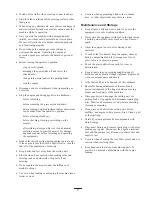
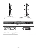
Page 7: ...edures Safety and Instruction Decals Safety decals and instructions are easily visible to the operator and are located near any area of potential danger Replace any decal that is damaged or lost Part No 93 7348 1 Danger readthe operator s manual 2 Fire or open flame sparks flame and smoking prohibited Fill the fuel tank no higher than to the bottom of the filler neck 3 Thrown object hazard keep by...

Page 8: ...e 2 Reel drive 3 Neutral 4 Forward 5 Lever engaged 6 Lever disengaged Part No 104 2621 1 Read operator s manual Part No 93 8064 1 Danger readthe operator s manual before performing maintenance 2 Cutting hazard to hands fingers and feet stop the engine before going near rotating reels Part No 105 2411 1 Transmission oil ...

Page 9: ...parking brake enclosed Handle Loop style 1 in 2 5 cm diameter with easy pull pin height adjustment operator selected Optional Transport tires Two quick detachable pneumatic tires 3 00 3 25 x 6 3 25 in 8 25 cm tread width 15 psi 1 03 bars tire pressure Reel construction 5 in 12 7 cm diameter 11 high strength low allow steel blades through hardened impact resistant Suspension Semi floating cutting u...

Page 10: ...15 Tournament Bedknife Part No 93 4263 1 8 in Bedknife Part No 93 4264 Clip Kit Part No 105 5325 Hour Meter Kit Part No 105 5350 Spark Arrester Kit Part No 98 3426 High Altitude Jet for altitudes of 3000 to 6000 ft Part No 98 8735 High Altitude Jet for altitudes above 6000 ft Part No 98 8736 Extended Micro cut Part No 104 7720 Operator Presence Kit Part No 105 5333 8 Blade Reel Assembly Part No 10...

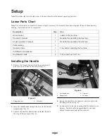
Page 11: ...he machine Certificate of compliance 1 Registration cards 2 Fill out and return to Toro Installing the Handle 1 Remove the flange lock nut from the capscrew and pivot pin on each side of the mower Fig 3 1 2 Figure 3 1 Flange lock nut 2 Pivot pin 2 Insert the handle ends through the slots in the handle support arms Fig 4 3 Squeeze the handle ends inward and install them on the step of the pivot pin...

Page 12: ... stand down with foot and pull up on handle to support mower on kick stand 2 Apply Anti Seize lubricant to the exposed ends of axles and slide wheel onto axle Fig 6 1 Figure 6 1 Left axle shaft 3 Pivot wheel locking clip away from center of wheel allowing wheel to slide farther onto axle Fig 7 4 Rotate wheel back and forth until it slides completely onto axle and locking clip is secured in groove ...

Page 13: ...r port Then remove and check level of oil Do not screw into port If level is low add only enough oil to raise level to bottom of filler opening Recheck level of oil Do not overfill Note The Toro Company recommends that the oil level be checked each time mower is used or after every 5 operating hours Initially change oil after the first 20 hours of operation thereafter change oil after every 50 hou...

Page 14: ...ct with the rim of the fuel tank or container opening at all times until fueling is complete 1 Clean around fuel tank cap and remove cap from tank Fig 9 Using unleaded gasoline fill fuel tank no higher than to bottom of filter screen Do not overfill 2 Install fuel tank cap and wipe up any spilled gasoline Checking the Transmission Fluid The transmission is filled at the factory with approximately ...

Page 15: ...d of the roller If the gap is greater than the piece of paper on either end an adjustment may be required proceed to step 4 4 Loosen locknuts securing right rear roller bracket to cutting unit sideplate Fig 14 1 2 Figure 14 1 Right rear roller bracket 2 Locknuts 5 While holding reel securely on plate and maintaining pressure on rear roller rotate lower right roller mounting bolt Fig 15 This mounti...

Page 16: ...contact at other end of reel using paper and adjust as required 5 After adjustment is accomplished check to see if reel can pinch paper when inserted from the front and cut paper when inserted at a right angle to the bedknife Fig 17 It should be possible to cut paper with minimum contact between the bedknife and the reel blades Should excessive reel drag be evident it will be either necessary to b...

Page 17: ... 7 Tighten nuts to secure adjustment Adjusting the Cut Off Bar Adjust cut off bar to assure clippings are cleanly discharged from the reel area 1 Loosen screws securing top bar Fig 21 to cutting unit 1 Figure 21 1 Cut off bar 2 Insert 060 inch feeler gauge between top of reel and bar and tighten screws Ensure bar and reel are equal distance apart across complete reel Note The bar is adjustable to ...

Page 18: ... is located on rear right side of control panel Lever connects to and operates throttle linkage to carburetor Engine speed can be varied from 2400 RPM to 3600 RPM 2 3 1 Figure 23 1 Throttle control 2 Traction reel drive engagement lever 3 Service parking brake Traction and Reel Drive Engagement Lever The traction and reel drive engagement lever Fig 23 is located on front right side of control pane...

Page 19: ...eel drive levers are in Disengaged position Note Engine will not start if traction lever is in the engaged position 2 Open fuel shut off valve on engine Fig 24 3 Move on off switch Fig 25 to On position 4 Move throttle control Fig 23 to Fast position 5 Move choke lever Fig 24 to half open position when starting a cold engine Choke may not be required when starting a warm engine 6 Pull recoil start...

Page 20: ...carefully adjusted and is set evenly on both sides of the reel Improper mower adjustment is magnified in the appearance of the clipped turf Remove all foreign objects from turf prior to mowing Make sure everyone especially children and pets are clear of the work area Method of Mowing The greens should be mowed in a straight back and forth direction across the green Avoid circular mowing or turning...

Page 21: ...rottle speed until the mower is traveling at the desired ground speed drive the mower out onto the green area lower the front of the mower down and commence operation Fig 28 After Mowing 1 Drive off green move reel drive and traction control levers to Disengage and stop the engine 2 Empty the grass catcher of clippings install grass catcher and commence transport operation refer to Transport Opera...

Page 22: ...lter pre cleaner Check for loose fasteners Every 50 hours Clean the fuel filter and sediment bowl Change the engine oil Check the transmission fluid level Every 100 hours Check the cut off bar adjustment Service the air cleaner filter Check the gear case oil level Every 200 hours Clean the combustion chamber Replace the spark plug Adjust the valves and torque the head bolts Every 2 years Replace s...

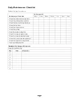
Page 23: ...peration Check that pivot joints operate freely Check the fuel level Check the engine oil level Check the air filter Clean the engine cooling fins Check for unusual engine noises Check for unusual operating noises Check the reel to bedknife adjustment Check the height of cut adjustment Touch up damaged paint Notation for Areas of Concern Inspection performed by Item Date Information 1 2 3 4 5 6 7 ...

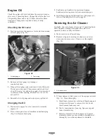
Page 24: ...ce a drain pan at rear of machine under drain plug Fig 29 Remove drain plug 3 Push down on handle to tip mower and engine backward allowing more oil to run into drain pan 4 Install drain plug and refill crankcase with proper oil refer to Checking the Oil Level page 24 Servicing the Air Cleaner Normally clean air cleaner after every 25 operating hours More frequent cleaning is required when mower i...

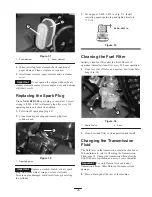
Page 25: ...electrodes because engine damaged could result from grit entering the cylinder 3 Set air gap at 0 028 0 032 in Fig 33 Install correctly gapped spark plug and tighten firmly to 17 ft lb 0 028 0 032 in Figure 33 Cleaning the Fuel Filter Initially clean fuel filter after the first 20 hours of operation thereafter clean after every 50 hours operation 1 Close fuel shut off valve and unscrew bowl from f...

Page 26: ...the bottom of the check fill hole refer to Checking the Transmission Fluid page 14 for proper oil type 7 Install the check fill plug Adjusting the Belts Make sure belts are properly tensioned to assure proper operation of the machine and unnecessary wear Check belts frequently Reel Drive Belt Reel 1 Remove the belt cover mounting fasteners and belt cover to expose belt Fig 36 1 Figure 36 1 Belt co...

Page 27: ...h here C Tighten the bearing housing mounting nuts Fig 38 Do not over tension belt D Install belt cover Reel Drive Belt Transmission coupler 1 Remove the belt cover mounting fasteners and belt cover to expose belt Fig 40 1 Figure 40 1 Belt cover 2 Check tension by depressing belt Fig 41 at mid span of pulleys with 4 1 lb of force Belt should deflect 1 4 in If deflection is incorrect proceed to nex...

Page 28: ...ring housing mounting nuts Fig 38 Do not over tension belt D Install belt cover Traction Drive Belt 1 Remove belt cover mounting fasteners and belt cover to expose belt Fig 44 1 Figure 44 1 Traction drive belt cover 2 Check tension by depressing belt Fig 45 at mid span of pulleys with 4 1 lb of force Belt should deflect 1 4 in If deflection is incorrect proceed to next step 1 Figure 45 1 Traction ...

Page 29: ...e 2 Service parking brake cable Adjusting the Service Parking Brake If service park brake slips when operated an adjustment is required 1 Move service parking brake lever to Off position 2 To increase cable tension loosen front cable jam nut and tighten back cable jam nut Fig 48 until a force of 6 9 lb is required to engage brake Force to be measured at lever knob Do not over adjust or brake band ...

Page 30: ... 2 years Servicing the Bedbar Removing the Bedbar 1 Turn bedbar adjuster screw counterclockwise to back bedknife away from reel Fig 51 1 2 3 4 5 Figure 51 1 Bedbar adjusting screw 2 Spring tension nut 3 Bedbar 4 Jam nut 5 Bedbar bolt 2 Back out the spring tension nut until the washer is no longer tensioned against the bedbar Fig 51 3 On each side of the machine loosen the jam nut securing the bedb...
Page 31: ...ning Reel and Rotary Mowers Manual Form No 80 300 PT Danger Contact with the reel or other moving parts can result in personal injury Stay away from the reel while backlapping Never use a short handled paint brush for backlapping Part No 29 9100 Handle assembly complete or individual parts are available from your local Authorized Toro Distributor Note For a better cutting edge run a file across th...

Page 32: ...eather storage practices contamination use of unapproved coolants lubricants additives or chemicals etc Normal wear and tear items Normal wear and tear includes but is not limited to damage to seats due to wear or abrasion worn painted surfaces scratched decals or windows etc Parts Parts scheduled for replacement as required maintenance are warranted for the period of time up to the scheduled repl...

Reviews: