15
Installing the Cutting Units
For Cutting Unit Models 04610 and 04611
Note:
When sharpening, setting the height-of-cut or
performing other maintenance procedures on the cutting
units, store the cutting unit reel motors in the support tubes
on the front of the frame to prevent damage to the hoses.
1.
Remove the cutting units from the cartons. Assemble
and adjust them as listed in the cutting unit
Operator’s
Manual
. Use the gauge bar from the loose parts kit to
adjust the height of cut.
2.
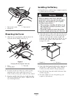
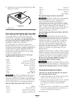
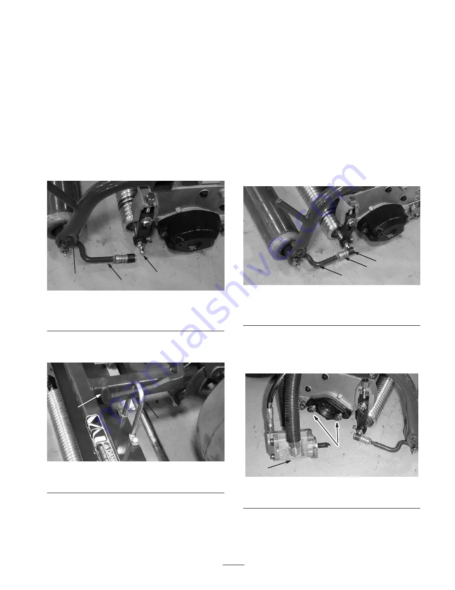
Mount a washer and ball stud to each end of the front
roller on the cutting units (Fig. 10).
1
2
3
Figure 10
1. Pull frame
2. Pull arm
3. Ball stud
3.
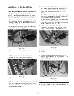
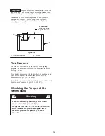
Slide the cutting unit under the pull frame while
hooking the
lift hook onto the lift arm (Fig. 11).
1
2
Figure 11
1. Lift arm
2. Lift hook
4.
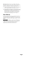
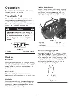
Slide the sleeve back on the ball joint and rotate the pull
arm down so the socket fits over the ball stud. Release
the sleeve so it slides over the stud and locks the
assemblies together (Fig. 12).
5.
Mount the baskets on the pull frames, loosen the jam
nuts on the pull arms, and adjust the ball sockets until
there is 1/4 to 1/2 in. (6 to 13 mm) clearance between
the lip of the basket and the reel blades or the front
shield.
Note:
This prevents the basket from tipping the cutting
unit forward, causing the lift roller to come off of the
lift arm while in the mowing operation.
Be sure the basket lip is equidistant from the reel blades
all across each reel. If the basket is too close to the reel,
it is possible for the reel to contact the basket when the
cutting unit is raised off of the ground.
6.
Align the sockets in the ball joints so the open side of
the socket is centered towards the ball stud. Tighten the
jam nuts to secure the sockets in position (Fig. 12).
1
2
3
Figure 12
1. Ball joint
2. Pull arm
3. Jam nut
7.
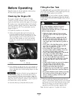
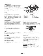
Assemble the
mounting capscrews for the reel drive
motor to each cutting unit. Leave approximately 1/2 in.
(13 mm) of threads exposed on each mounting
capscrew (Fig. 13).
1
2
Figure 13
1. Capscrews
2. Drive motor
8.
Remove the protective covers from the cutting units and
the reel drive motor shafts.
Summary of Contents for 04351 Greensmaster 3050
Page 40: ...40 Hydraulic Schematic ...
Page 46: ...46 ...

