35
Adjusting the Traction Pedal
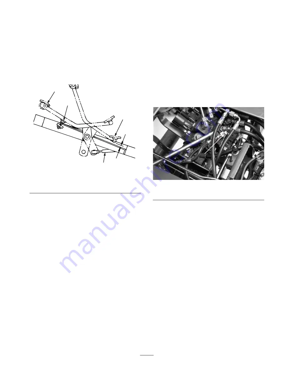
To check the forward and reverse operation of the traction
pedal, proceed as follows:
Adjusting Forward
1.
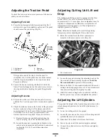
Press the traction pedal fully forward until the No. 5
section valve spool is completely pulled out. The pedal
should contact the pedal stop (Fig. 48).
1
2
3
4
3/16 in.
(5 mm)
Figure 48
1. Fully forward
2. Pedal stop
3. Reverse
4. Control rod
If the pedal contacts the stop before the spool is
completely out, or if the pedal does not make contact
with the stop, an adjustment to the stop is necessary.
Proceed as follows:
2.
Loosen the hex nut securing the threaded rod to the
frame. Turn the flange nut on the rod to raise or lower
the stop (rod) while checking the pedal. Retighten the
nut.
Adjusting Reverse
1.
Press down on the rear of the traction pedal (reverse)
until the No. 5 section spool valve is completely pushed
in.
2.
Check the distance between the bottom of the pedal and
footrest as shown in Fig. 48. The distance shouId be
approximately 3/16 in. (5 mm). If the distance is greater
or less than 3/16 in. (5 mm), an adjustment to the
traction control rod is required. Proceed as follows:
A. Remove the jam nut and ball joint securing the
control rod (Fig. 48) to the traction shaft pivot.
B. Loosen the jam nuts securing the ball joints to the
control rod and adjust the ball joints and control rod
to attain the 3/16 in. (5 mm) dimension when
reinstalled.
Adjusting Cutting Unit Lift and
Drop
The cutting unit lift/drop circuit is equipped with a flow
control valve. This valve is preset at the factory at
approximately 3-1/2 turns open, but an adjustment may be
required to compensate for differences in hydraulic oil
temperatures, mowing speeds, etc. If an adjustment is
required, proceed as follows:
Note:
Allow the hydraulic oil to reach full operating
temperature before adjusting the flow control valve.
1.
Raise the seat and locate the flow control valve
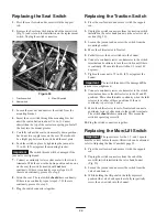
mounted to the main control valve (Fig. 49).
1
Figure 49
1. Flow control valve
2.
Loosen the jam nut retaining the adjusting knob on the
flow control. When loosening the jam nut,
hold the
flow control knob
to prevent it from rotating.
3.
Rotate the knob 1/4 turn counterclockwise if the center
cutting unit is dropping too late or 1/4 turn clockwise if
the center cutting unit is dropping too early.
4.
After the desired setting has been achieved, hold the
knob to prevent any rotation and tighten the jam nut.
Adjusting the Lift Cylinders
To regulate the height of the front cutting units when in the
raised (transport) position, the front lift cylinders may be
adjusted.
1.
Lower the cutting units to the ground.
2.
Loosen the jam nut, on the clevis, of the cutting unit lift
cylinder that needs to be adjusted.
3.
Disconnect the cylinder clevis from the lift arm.
4.
Rotate the clevis until the desired height is attained.
5.
Connect the cylinder clevis to the lift arm and tighten
the jam nut.
Summary of Contents for 04351 Greensmaster 3050
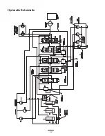
Page 40: ...40 Hydraulic Schematic ...
Page 46: ...46 ...

