Greensmaster 3300/3400
Page 7 -- 23
Chassis
Removal (Fig. 18)
1. Park machine on a level surface, engage the parking
brake, lower the cutting units and stop the engine. Re-
move key from the ignition switch.
2. Remove grass basket from suspension assembly.
3. Remove cutting unit from suspension assembly (see
Traction Unit Operator’s Manual).
4. If front suspension assembly is to be removed, re-
move front wheel (see Wheel Removal in this section).
This will allow easier access to flange head screws that
secure suspension assembly to frame.
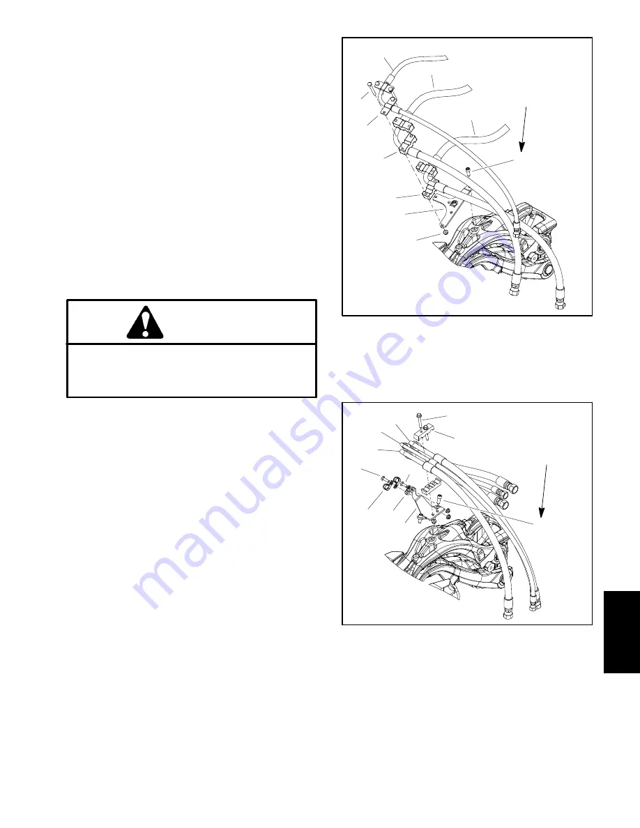
5. Remove hydraulic hose bracket from suspension as-
sembly (Fig. 19 or 20).
6. Position and support reel motor and attached hy-
draulic hoses away from suspension assembly.
CAUTION
Support suspension assembly when removing it
to prevent it from falling and causing personal in-
jury. Suspension assembly weighs approximate-
ly 65 pounds (30 kg).
7. Support suspension assembly to prevent it from
shifting or falling.
8. Remove three (3) flange head screws (item 2) that
secure suspension assembly to machine frame. Re-
move suspension assembly from machine.
Installation (Fig. 18)
1. Make sure that all suspension components are cor-
rectly assembled.
2. Position suspension assembly to frame. Align
mounting holes and secure suspension with three (3)
flange head screws (item 2). Torques screws from
55 to
60 ft--lb (75 to 81 N--m)
.
3. Position reel motor and attached hydraulic hoses to
suspension assembly. Insert reel motor shaft into stor-
age location on front of suspension assembly.
4. Secure hydraulic hose bracket to suspension as-
sembly (Fig. 19 or 20). Torque two (2) socket head
screws from
85 to 115 in--lb (9.6 to 12.9 N--m)
.
5. Install cutting unit to suspension assembly (see
Traction Unit Operator’s Manual).
6. Install grass basket to suspension assembly.
1. Cap screw (4 used)
2. Strap (2 used)
3. Tube clamp (4 used)
4. Hose bracket
5. Flange nut (4 used)
6. Socket screw (2 used)
7. Case drain hose
8. Pressure hose
9. Return hose
Figure 19
5
3
2
4
1
3
6
9
8
7
FRONT CUTTING UNIT
85 to 115 in--lb
(9.6 to 12.9 N--m)
1. Screw (2 used)
2. Tube clamp (2 used)
3. Cap screw
4. R--clamp (2 used)
5. R--clamp
6. Hose bracket
7. Socket screw (2 used)
8. Cap screw
9. Pressure hose
10. Case drain hose
11. Return hose
Figure 20
9
10
11
6
2
7
8
4
3
5
1
CENTER CUTTING UNIT
85 to 115 in--lb
(9.6 to 12.9 N--m)
Chassis
Summary of Contents for 04510 Greensmaster 3300 TriFlex
Page 2: ...Greensmaster 3300 3400 This page is intentionally blank ...
Page 4: ...Greensmaster 3300 3400 This page is intentionally blank ...
Page 6: ...Greensmaster 3300 3400 This page is intentionally blank ...
Page 24: ...Greensmaster 3300 Page 3 6 Gasoline Engine This page is intentionally blank ...
Page 38: ...Greensmaster 3400 Page 4 4 Diesel Engine This page is intentionally blank ...
Page 54: ...Greensmaster 3300 3400 Hydraulic System Page 5 2 This page is intentionally blank ...
Page 170: ...Greensmaster 3300 3400 Hydraulic System Page 5 118 This page is intentionally blank ...
Page 172: ...Greensmaster 3300 3400 Page 6 2 Electrical System This page is intentionally blank ...
Page 230: ...Greensmaster 3300 3400 Page 6 60 Electrical System This page is intentionally blank ...
Page 303: ...Greensmaster 3300 3400 Groomer Page 9 13 This page is intentionally blank Groomer ...
Page 318: ...Greensmaster 3300 3400 Page 10 2 Foldout Drawings This page is intentionally blank ...
Page 332: ...Page 10 16 This page is intentionally blank ...


