Greensmaster 3300/3400
Hydraulic System
Page 5 -- 32
Testing
The most effective method for isolating problems in the
hydraulic system is by using hydraulic test equipment
such as pressure gauges and flow meters in the circuits
during various operational checks (see the Special
Tools section in this Chapter).
IMPORTANT: All obvious areas such as oil supply,
filter, binding linkages, loose fasteners, improper
adjustments, solenoid valve operation or electrical
connections must be checked before assuming that
a hydraulic component is the source of the problem.
Before disconnecting or performing any work on
the hydraulic system, all pressure in the system
must be relieved and all rotating machine parts
must be stopped. See Relieving Hydraulic Sys-
tem Pressure in the General Information section.
WARNING
CAUTION
Failure to use gauges with recommended pres-
sure (PSI) rating as listed in test procedures
could result in damage to the gauge and possible
personal injury from leaking hot oil.
CAUTION
All testing should be performed by two (2)
people. One person should be in the seat to oper-
ate the machine and the other should monitor
testing equipment and record test results.
Keep body and hands away from pin hole leaks
or nozzles that eject hydraulic fluid under high
pressure. Do not use hands to search for leaks;
use paper or cardboard. Hydraulic fluid escap-
ing under pressure can have sufficient force to
penetrate the skin and cause serious injury. If
fluid is injected into the skin, it must be surgical-
ly removed within a few hours by a doctor famil-
iar with this type of injury. Gangrene may result
from such an injury.
WARNING
Precautions for Hydraulic Testing
1. Clean machine thoroughly before disconnecting or
disassembling any hydraulic components. Always keep
in mind the need for cleanliness when working on hy-
draulic equipment. Contamination will cause excessive
wear of components.
2. To prevent hydraulic system contamination, put met-
al caps or plugs on any hydraulic lines left open or ex-
posed during testing or removal of components.
3. The engine must be in good operating condition. En-
gine speed will affect test accuracy. Check pump speed
with a phototac when performing hydraulic tests.
4. When using tester with pressure and flow capabili-
ties, the inlet and the outlet hoses must be properly con-
nected and not reversed to prevent damage to the
hydraulic tester or other components.
5. When using tester with pressure and flow capabili-
ties, completely open load valve in the hydraulic tester
to minimize the possibility of damaging components.
6. Install fittings finger tight and far enough to make
sure that they are not cross--threaded before tightening
them with a wrench.
7. Position tester hoses to prevent rotating machine
parts from contacting and damaging the hoses or tester.
8. Check oil level in the hydraulic reservoir. After con-
necting test equipment, make sure tank is full.
9. Check control linkages for improper adjustment,
binding or broken parts.
10.All hydraulic tests should be made with the hydraulic
oil at normal operating temperature.
11.Record the results of all performed hydraulic tests.
Which Hydraulic Tests Are Necessary?
Before beginning any hydraulic test, identify if the prob-
lem is related to the traction circuit, mow circuit, lift/lower
circuit or steering circuit. Once the faulty system has
been identified, perform tests that relate to that circuit.
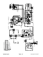
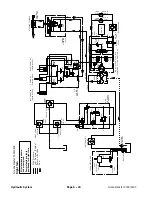
1. Use the Hydraulic Schematic, Hydraulic Flow Dia-
grams and the Troubleshooting section found in this
Chapter to assist in hydraulic problem identification and
solution.
2. Hydraulic system problems (e.g. low hydraulic oil
level, contaminated oil, incorrect engine speed) will af-
fect the entire hydraulic system.
Summary of Contents for 04510 Greensmaster 3300 TriFlex
Page 2: ...Greensmaster 3300 3400 This page is intentionally blank ...
Page 4: ...Greensmaster 3300 3400 This page is intentionally blank ...
Page 6: ...Greensmaster 3300 3400 This page is intentionally blank ...
Page 24: ...Greensmaster 3300 Page 3 6 Gasoline Engine This page is intentionally blank ...
Page 38: ...Greensmaster 3400 Page 4 4 Diesel Engine This page is intentionally blank ...
Page 54: ...Greensmaster 3300 3400 Hydraulic System Page 5 2 This page is intentionally blank ...
Page 170: ...Greensmaster 3300 3400 Hydraulic System Page 5 118 This page is intentionally blank ...
Page 172: ...Greensmaster 3300 3400 Page 6 2 Electrical System This page is intentionally blank ...
Page 230: ...Greensmaster 3300 3400 Page 6 60 Electrical System This page is intentionally blank ...
Page 303: ...Greensmaster 3300 3400 Groomer Page 9 13 This page is intentionally blank Groomer ...
Page 318: ...Greensmaster 3300 3400 Page 10 2 Foldout Drawings This page is intentionally blank ...
Page 332: ...Page 10 16 This page is intentionally blank ...


