Greensmaster 3300/3400
Hydraulic System
Page 5 -- 45
The steering/lift circuit gear pump flow test should be
performed to make sure that the steering, lift and trac-
tion charge circuits have adequate hydraulic flow.
Procedure for Steering/Lift Circuit Gear Pump Flow
Test:
1. Make sure hydraulic oil is at normal operating tem-
perature by operating the machine for approximately ten
(10) minutes.
2. Park machine on a level surface with the cutting units
lowered. Make sure engine is off and the parking brake
is engaged. Make sure the hydraulic tank is full.
CAUTION
Prevent personal injury and/or damage to equip-
ment. Read all WARNINGS, CAUTIONS and Pre-
cautions for Hydraulic Testing at the beginning
of this section.
3. Thoroughly clean junction of hydraulic hose and dis-
charge fitting of rear gear pump section (Fig. 25). Dis-
connect hose from pump fitting.
4. Install hydraulic tester (pressure and flow) in series
with the rear gear pump section and the disconnected
hose. Make sure that tester flow arrow points from the
pump discharge and toward the disconnected hose.
Also, make sure flow control valve on the tester is
fully open.
5. Make sure that traction pedal and joystick are in neu-
tral and the parking brake is engaged.
6. Start engine and run at low idle speed. Check for hy-
draulic leakage and correct before proceeding with test.
7. Move throttle so engine is running at high idle speed.
IMPORTANT: Do not fully restrict oil flow through
tester. In this test, the flow tester is positioned be-
fore the circuit relief valve. Pump damage can occur
if the oil flow is fully restricted.
8. Watch flow and pressure gauge carefully while slow-
ly closing the flow control valve on the tester until the
pressure gauge reads
800 PSI (55.2 bar)
.
9. Flow gauge reading for a gear pump in good condi-
tion should be approximately
3.9 GPM (14.8 LPM)
.
10.Open control valve on tester and shut off engine. Re-
cord test results.
11.If gear pump flow is less than
3.5 GPM (13.2 LPM)
,
check for restriction in the pump intake line. If no restric-
tion is found, repair or replace rear gear pump section.
12.When testing is complete, disconnect tester from the
gear pump fitting and hydraulic hose. Connect hose to
pump fitting.
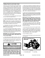
1. Gear pump
2. Rear section fitting
Figure 25
GR3300 GEAR PUMP SHOWN
2
1
Hydraulic System
Summary of Contents for 04510 Greensmaster 3300 TriFlex
Page 2: ...Greensmaster 3300 3400 This page is intentionally blank ...
Page 4: ...Greensmaster 3300 3400 This page is intentionally blank ...
Page 6: ...Greensmaster 3300 3400 This page is intentionally blank ...
Page 24: ...Greensmaster 3300 Page 3 6 Gasoline Engine This page is intentionally blank ...
Page 38: ...Greensmaster 3400 Page 4 4 Diesel Engine This page is intentionally blank ...
Page 54: ...Greensmaster 3300 3400 Hydraulic System Page 5 2 This page is intentionally blank ...
Page 170: ...Greensmaster 3300 3400 Hydraulic System Page 5 118 This page is intentionally blank ...
Page 172: ...Greensmaster 3300 3400 Page 6 2 Electrical System This page is intentionally blank ...
Page 230: ...Greensmaster 3300 3400 Page 6 60 Electrical System This page is intentionally blank ...
Page 303: ...Greensmaster 3300 3400 Groomer Page 9 13 This page is intentionally blank Groomer ...
Page 318: ...Greensmaster 3300 3400 Page 10 2 Foldout Drawings This page is intentionally blank ...
Page 332: ...Page 10 16 This page is intentionally blank ...


