background image

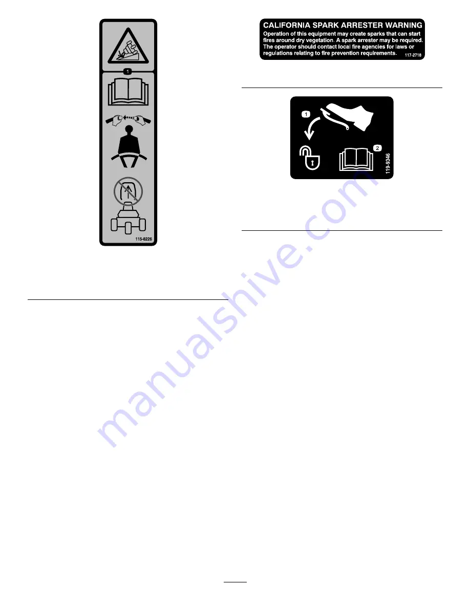
decal115-8226

115-8226

1.

Tipping hazard—read the

Operator's Manual

; always wear

a seat belt when operating; do not remove the rollover
protection system (ROPS).

decal117-2718

117–2718

decal119-9346

119-9346

1.

Press the pedal to unlock.

2.

Read the

Operator's

Manual

for more

information.

5


Summary of Contents for 04510 Greensmaster 3300 TriFlex

Page 1: ...Form No 3419 302 Rev A Greensmaster 3300 TriFlex Traction Unit Model No 04510 Serial No 401390001 and Up Register at www Toro com Original Instructions EN 3419 302 A ...

Page 2: ...imize the safety performance and proper operation of this machine carefully read and fully understand the contents of this Operator s Manual Failing to follow these operating instructions or to receive proper training may result in injury For more information on safe operating practices including safety tips and training materials go to www Toro com Whenever you need service genuine Toro parts or ...

Page 3: ...ing the Machine 25 Towing the Machine 26 Maintenance 27 Recommended Maintenance Schedule s 28 Daily Maintenance Checklist 29 Pre Maintenance Procedures 30 Pre Maintenance Safety 30 Engine Maintenance 30 Engine Safety 30 Servicing the Air Cleaner 30 Servicing the Engine Oil 31 Replacing the Spark Plugs 32 Fuel System Maintenance 32 Replacing the Fuel Filter 32 Inspecting the Fuel Lines and Connecti...

Page 4: ...achine Keep children out of the operating area Never allow children to operate the machine Stop the machine and shut off the engine before servicing fueling or unclogging the machine Improperly using or maintaining this machine can result in injury To reduce the potential for injury comply with these safety instructions and always pay attention to the safety alert symbol which means Caution Warnin...

Page 5: ...read the Operator s Manual always wear a seat belt when operating do not remove the rollover protection system ROPS decal117 2718 117 2718 decal119 9346 119 9346 1 Press the pedal to unlock 2 Read the Operator s Manual for more information 5 ...

Page 6: ...er and engage the reels 9 Reel mow 4 Raise and disengage the reels 10 Reel backlaping 5 Reel speed fast 11 Move forward 6 Reel speed slow decal132 9549 132 9549 1 Read the Operator s Manual before servicing or performing maintenance 4 Engine start 2 Hydraulic fluid level 5 Engine run 3 Choke 6 Engine stop 6 ...

Page 7: ...al136 8505 136 8505 Replaces Decal 136 8506 for CE Machines Note This machine complies with the industry standard stability test in the static lateral and longitudinal tests with the maximum recommended slope indicated on the decal Review the instructions for operating the machine on slopes in the Operator s Manual as well as the conditions in which you would operate the machine to determine wheth...

Page 8: ...decal115 8156 115 8156 1 Reel height 3 8 Blade cutting unit 5 14 Blade cutting unit 7 Fast 2 5 Blade cutting unit 4 11 Blade cutting unit 6 Reel speed 8 Slow decal119 9345 119 9345 8 ...

Page 9: ...ange bolts 12 Install the grass basket hooks Gauge bar 1 Cutting unit obtain from your authorized Toro Distributor 3 7 Grass basket 3 Install the cutting units 8 Weight kit Part No 119 7129 sold separately 1 Add rear weight Warning decal Part No 136 8505 1 9 CE mark decal 1 Install the CE decals if required 10 No parts required Reduce the tire pressure 11 No parts required Burnish the brakes Media...

Page 10: ...rocedure Note Mount the seat in the front set of mounting holes to gain an additional 7 6 cm 3 inches in the forward adjustment or in the rear mounting holes for an additional 7 6 cm 3 inches in the rearward adjustment 1 Remove and discard the lag bolts securing the seat slides and cut the shipping straps 2 Remove the 4 bolts 5 16 x 3 4 inch and washers from the shipping bracket and discard the br...

Page 11: ...ill the battery initially WARNING CALIFORNIA Proposition 65 Warning Battery posts terminals and related accessories contain lead and lead compounds chemicals known to the State of California to cause cancer and reproductive harm Wash hands after handling WARNING Battery terminals or metal tools could short against metal tractor components causing sparks Sparks can cause the battery gasses to explo...

Page 12: ... electrical outlet and battery posts Note After the battery has been activated add only distilled water to replace normal loss although maintenance free batteries should not require water under normal operating conditions Important Failure to correctly activate the battery may result in battery gassing and or premature battery failure 7 Install the vent caps 8 Place the battery on the battery tray...

Page 13: ... Hooks Parts needed for this procedure 6 Grass basket hook 12 Flange bolts Procedure Install the 6 grass basket hooks onto the ends of the suspension arm bars using the 12 flange bolts Figure 9 g015492 Figure 9 1 Flange bolt 3 Suspension arm bar 2 Grass basket hook 7 Installing the Cutting Units Parts needed for this procedure 1 Gauge bar 3 Cutting unit obtain from your authorized Toro Distributor...

Page 14: ... CE warning decal Part No 136 8505 over the existing warning decal Part No 136 8506 Apply the CE mark decal to the frame under the front of the seat Figure 10 g233420 Figure 10 1 CE mark decal 10 Reducing the Tire Pressure No Parts Required Procedure The tires are overinflated at the factory for shipping purposes Reduce the pressure to the proper levels before starting the machine refer to Checkin...

Page 15: ...e traction pedal when you are driving the machine forward Figure 13 g014603 Figure 12 1 Traction pedal forward 3 Steering arm locking pedal 2 Taction pedal reverse g005105 Figure 13 Ground speeds are as follows 3 2 to 8 km h 2 to 5 mph forward mowing speed 16 km h 10 mph maximum transport speed 4 0 km h 2 5 mph reverse speed Steering Arm Locking Pedal Press the pedal Figure 12 and raise or lower t...

Page 16: ...ition neutral position use when backlapping the reels MIDDLE position use when cutting grass FRONT position use when driving the machine between job sites Ignition Switch Insert the key into the switch Figure 14 and turn it clockwise to the START position to start the engine Release the key as soon as the engine starts the key moves to the ON position Turn the key counterclockwise to the STOP posi...

Page 17: ...ontrol lever and the reel speed control for backlapping the reels g014620 Figure 17 1 Backlap lever mow position 2 Backlap lever backlap position Reel Speed Control The reel speed control is located under the plastic cover to the left of the seat Use the reel speed control Figure 18 to adjust the speed of the reels g014623 Figure 18 1 Reel speed control Seat Adjusting Lever The seat adjusting leve...

Page 18: ...l width 179 cm 70 6 inches Overall height 205 cm 80 8 inches Net Weight w reels 8 Blade 633 kg 1 395 lb Attachments Accessories A selection of Toro approved attachments and accessories is available for use with the machine to enhance and expand its capabilities Contact your Authorized Service Dealer or Distributor or go to www Toro com for a list of all approved attachments and accessories To best...

Page 19: ...re there is an open flame spark or pilot light such as on a water heater or other appliance If you spill fuel do not attempt to start the engine avoid creating any source of ignition until the fuel vapors have dissipated Fuel Specification Fuel tank capacity 26 6 L 7 US gallons Recommended Fuel Unleaded gasoline with an octane rating of 87 or higher R M 2 rating method Ethanol Gasoline with up to ...

Page 20: ...ired or under the influence of alcohol or drugs Never carry passengers on the machine and keep bystanders and pets away from the machine during operation Operate the machine only in good visibility to avoid holes or hidden hazards Avoid mowing on wet grass Reduced traction could cause the machine to slide Before you start the engine ensure that all drives are in neutral the parking brake is engage...

Page 21: ...tion for the machine Avoid starting stopping or turning the machine on slopes Avoid making sudden changes in speed or direction Make turns slowly and gradually Do not operate a machine under any conditions where traction steering or stability is in question Remove or mark obstructions such as ditches holes ruts bumps rocks or other hidden hazards Tall grass can hide obstructions Uneven terrain cou...

Page 22: ... the bearings and reels are tight it is necessary to use the FAST throttle lever position for this check A fast throttle setting may not be required after the break in period Note If fluid leaks continue to appear contact your authorized Toro distributor for assistance and if necessary replacement parts Important A trace of fluid on the motor or wheel seals is normal Seals require a small amount o...

Page 23: ...gine should shut off which indicates that the interlock system is operating correctly Correct the problem if it is not operating properly Checking the Raise Lower Mow Control 1 Sit on the seat move the traction pedal to the NEUTRAL position move the functional control lever to the NEUTRAL position and engage the parking brake 2 Start the engine 3 Move the raise lower mow control forward to lower t...

Page 24: ...ful to include the outer edge of the steering wheel as part of the sight line i e keep the steering wheel edge aligned with a point that is always kept the same distance away from the front of the machine 5 As the front edges of the baskets cross the edge of the green pull back the raise lower mow lever rearward and hold it until all the cutting units have risen This stops the reels and lifts the ...

Page 25: ...el while storing or transporting the machine Allow the engine to cool before storing the machine in any enclosure Never store the machine or fuel container where there is an open flame spark or pilot light such as on a water heater or on other appliances Inspecting and Cleaning after Mowing After mowing thoroughly wash the machine with a garden hose without a nozzle so that excessive water pressur...

Page 26: ... the machine more than 0 4 km 1 4 mile transport it on a truck or trailer 1 Locate the bypass valve on the pump and rotate it so that the slot is vertical Figure 25 g014627 Figure 25 1 Bypass valve slot shown in closed horizontal position 2 Before starting the engine close the bypass valve by rotating it so that the slot is horizontal Figure 25 Important Do not start the engine when the bypass val...

Page 27: ... free copy of the electrical or hydraulic schematic by visiting www Toro com and searching for your machine from the Manuals link on the home page Important Refer to your engine Owner s Manual for additional maintenance procedures CAUTION If you leave the key in the ignition switch someone could accidently start the engine and seriously injure you or other bystanders Remove the key from the igniti...

Page 28: ... to bedknife contact Every 50 hours Service the air cleaner foam element more frequently when operating conditions are dusty or dirty Check the battery electrolyte level If machine is in storage check the electrolyte level every 30 days Check the battery cable connections Every 100 hours Service the air cleaner paper element more frequently when operating conditions are dusty or dirty Change the e...

Page 29: ... operation Check the fuel level Check the hydraulic fluid level Check the engine oil level Clean the engine air cooling fins Inspect the air filter pre cleaner Check any unusual engine noises Check the reel to bedknife adjustment Check the hydraulic hoses for damage Check for fluid leaks Check the tire pressure Check the height of cut adjustment Touch up damaged paint Notation for Areas of Concern...

Page 30: ...ored energy Engine Maintenance Engine Safety Shut off the engine before checking the oil or adding oil to the crankcase Do not change the governor speed or overspeed the engine Servicing the Air Cleaner Service Interval Every 50 hours Service the air cleaner foam element more frequently when operating conditions are dusty or dirty Every 100 hours Service the air cleaner paper element more frequent...

Page 31: ...ition the machine on a level surface 2 Unscrew the dipstick remove it and wipe it with a clean rag 3 Insert the dipstick into the dipstick tube and thread it into the tube Figure 28 g005111 Figure 28 1 Dipstick 2 Filler cap 4 Unscrew the dipstick pull it out of the tube and check the oil level 5 If the oil level is low remove the filler cap from the valve cover and add oil into the engine through ...

Page 32: ...ngine 4 Set the air gap between the center and side of the electrodes at 0 76 mm 0 030 inch as shown in Figure 30 g002724 Figure 30 5 Install the spark plug and gasket seal and torque the plug to 23 N m 200 in lb Fuel System Maintenance Replacing the Fuel Filter Service Interval Every 800 hours sooner if the fuel flow is restricted The in line fuel filter is in the fuel line between the fuel tank ...

Page 33: ... causes severe burns Do not drink electrolyte and avoid contact with skin eyes or clothing Wear safety glasses to shield your eyes and rubber gloves to protect your hands Fill the battery where clean water is always available for flushing the skin 1 Check the electrolyte level in the in the cells of the battery 2 If needed add distilled or demineralized water into the cell of the battery Note Rais...

Page 34: ...n proper torque of the wheel nuts could result in personal injury Torque the wheel nuts to the specified torque at the specified intervals Wheel nut torque specification 95 to 122 N m 70 to 90 ft lb Note To ensure even distribution torque the wheel nuts in a X pattern Adjusting the Transmission for Neutral If the machine creeps when the traction control pedal is in the NEUTRAL position adjust the ...

Page 35: ... and press down on the traction pedal If the pedal contacts the stop Figure 34 before you feel tension on the cable perform the following adjustment procedure g015494 Figure 34 1 Pedal stop 1 Put the functional control lever in the TRANSPORT position and loosen the locknut securing the pedal stop to the floor plate Figure 34 2 Tighten the pedal stop until it does not contact the traction pedal 3 C...

Page 36: ... pedal pivot to lock the adjustment Figure 35 Check the adjustment and adjust as required Brake Maintenance Adjusting the Brakes If the brake fails to hold the machine while parked you can adjust the brakes using the bulkhead fitting near the brake drum contact your Authorized Service Distributor or refer to the Service Manual for more information Note Burnish the brakes annually refer to 11 Burni...

Page 37: ...286 S Quality Level Vickers M 2950 S Quality Level Denison HF 0 Important The ISO VG 46 Multigrade fluid has been found to offer optimal performance in a wide range of temperature conditions For operation in consistently high ambient temperatures 18 C 65 F to 49 C 120 F ISO VG 68 hydraulic fluid may offer improved performance Premium Biodegradable Hydraulic Fluid Mobil EAL EnviroSyn 46H Important ...

Page 38: ...sufficient g228586 Figure 37 1 Dipstick 2 Hydraulic tank 3 Remove the dipstick and wipe it with a clean rag then screw the dipstick back into the tank 4 Remove the dipstick and check the fluid level If the fluid is between the marks on the dipstick the level is sufficient If the fluid level is not between the marks more fluid is needed 5 Remove the cap from the hydraulic fluid tank and slowly fill...

Page 39: ...Hydraulic Lines and Hoses WARNING Hydraulic fluid escaping under pressure can penetrate skin and cause injury Ensure that all hydraulic fluid hoses and lines are in good condition and all hydraulic connections and fittings are tight before applying pressure to the hydraulic system Keep your body and hands away from pinhole leaks or nozzles that eject high pressure hydraulic fluid Use cardboard or ...

Page 40: ...d level down 118 to 177 ml 4 to 6 oz 3 Fluid level warm 2 Warning buzzer Checking the System Operation 1 With ignition switch in the ON position move the leak detector switch rearward and hold After the 1 second delay elapses the alarm should sound 2 Release the leak detector switch Checking the Leak Detector System Operation 1 Move the ignition switch to the ON position Do not start the engine 2 ...

Page 41: ... workload To avoid false alarms turn the machine off rather than idling for extended periods Cutting Unit Maintenance Cutting Unit Safety A worn or damaged blade or bed knife can break and a piece could be thrown at you or bystanders resulting in serious personal injury or death Inspect the blades and bed knives periodically for excessive wear or damage Use care when checking the blades Wear glove...

Page 42: ...gure 45 push the suspension arm down so that the bar fits over the bar across the top of the cutting unit Figure 46 g014609 Figure 45 1 Latch closed position 3 Latch open position 2 Suspension arm bar g014611 Figure 46 1 Suspension arm bar 2 Cutting unit bar 4 Close the latches down and around the cutting unit bar and lock them in place Figure 45 Note You can hear a click and feel when the latches...

Page 43: ... the suspension arm Figure 49 g014608 Figure 49 Note When sharpening setting the height of cut or performing other maintenance procedures on the cutting units store the cutting unit reel motors in the storage location on the front of the suspension arms to prevent damage to them Important Do not raise the suspension to the transport position when the reel motors are in the holders in the machine f...

Page 44: ...y rotating the knob Figure 51 until the indicator arrows are in line with the number you determined in step 3 g014623 Figure 51 1 Reel speed control Note You can increase or decrease the reel speed to compensate for turf conditions Backlapping the Reels WARNING Contact with the reels or other moving parts can result in personal injury Keep your fingers hands and clothing away from the reels or oth...

Page 45: ... until the speed stabilizes then return the reel speed to setting 1 or to your desired speed 10 To make an adjustment to the cutting units while backlapping turn the reels off by moving the raise lower mow control rearward and shut off the engine After completing adjustments repeat steps 4 through 8 11 Repeat the procedure for all cutting units you want to backlap 12 When finished return the backl...

Page 46: ...osition 7 Count the codes as they begin to flash you may release the raise lower mow control once they begin flashing When finished turn the key to the OFF position to exit diagnostic mode Determining the Error Code The system will display the last 3 faults that occurred in the last 40 hours It displays the faults through a series of blinking lights as follows If there are no faults the light will...

Page 47: ... removed from the fuel tank Run the engine until it stops Replace the fuel filter refer to Replacing the Fuel Filter page 32 5 While the engine is still warm drain the oil from the crankcase Refill it with fresh oil refer to Changing the Engine Oil and Filter page 31 6 Remove the spark plugs pour one ounce of SAE 30 oil into the cylinders and crank slowly to distribute the oil Replace the spark pl...

Page 48: ...Notes ...

Page 49: ...Notes ...

Page 50: ...Notes ...

Page 51: ...f these activities We will not sell your personal information to any other company We reserve the right to disclose personal information in order to comply with applicable laws and with requests by the appropriate authorities to operate our systems properly or for our own protection or that of other users Retention of your Personal Information We will keep your personal information as long as we n...

Page 52: ...to damage to seats due to wear or abrasion worn painted surfaces scratched decals or windows etc Parts Parts scheduled for replacement as required maintenance are warranted for the period of time up to the scheduled replacement time for that part Parts replaced under this warranty are covered for the duration of the original product warranty and become the property of Toro Toro will make the final...

Reviews: