Setup
Media and Additional Parts
Description
Qty.
Use
Operator's Manual
1
Read before installing and operating cutting unit
Parts catalog
1
Use to reference part numbers
Installing the Front Roller
The cutting unit is shipped without a front roller. Install the
roller using the loose parts supplied with the cutting unit and
installation instructions included with the roller.
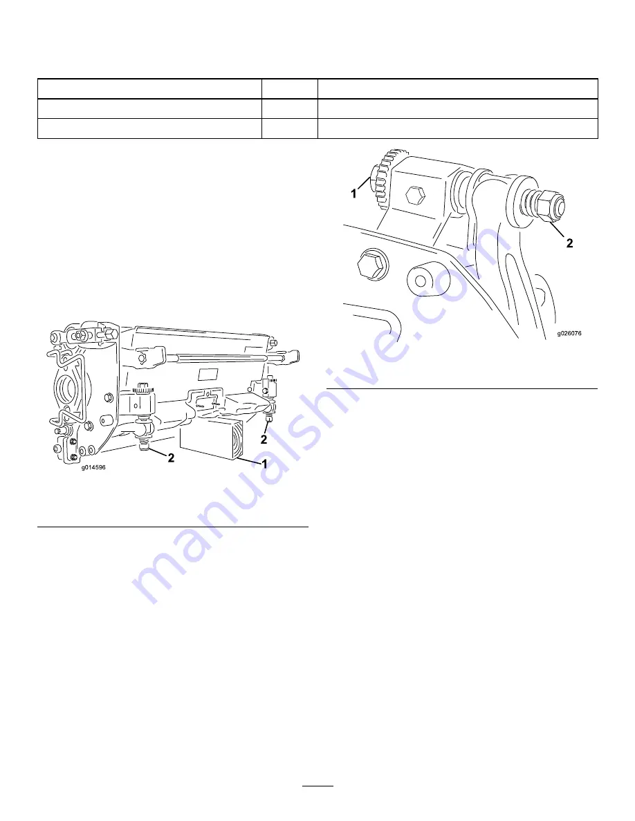
Using the Cutting Unit Prop
Whenever the cutting unit has to be tipped to expose the
bedknife/reel, prop up the rear of the cutting unit to make
sure the nuts on the back end of the bedbar adjusting screws
are not resting on the work surface (Figure 3).
g014596
1
2
2
Figure 3
1.
Prop (not provided)
2.
Bedknife adjusting screw
nut (2)
Adjusting the Bedknife to the
Reel
Note:
Use this procedure after grinding, backlapping, or
disassembly. It is not intended as a daily adjustment.
1.
Position the cutting unit on a flat, level work surface.
2.
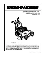
Tip the cutting unit to expose the bedknife and the
reel.
Make sure the nuts or the back of the bedbar
adjusting screws are not resting on the work
surface (Figure 4)
.
g026076
1
2
Figure 4
1.
Bedknife adjusting screw
2.
Nut
3.
Rotate the reel so that a blade crosses the bedknife edge
between the first and second bedknife screw heads on
the right side of the cutting unit.
4.
Put an identifying mark on the blade where it
crosses the bedknife edge; this will make subsequent
adjustments easier.
5.
Insert the .05 mm (0.002 inch) shim between the
marked blade and the bedknife edge at the point where
the marked blade crosses the bedknife edge.
6.
Turn the right bedbar adjusting screw until you feel
light pressure (i.e. drag) on the shim by sliding it
side-to-side. Remove the shim.
7.
For the left side of the cutting unit, slowly rotate the
reel so that the closest blade crosses the bedknife edge
between the first and second screw heads.
8.
Repeat steps 4 through 6 for the left side of the cutting
unit and left bedbar adjusting screw.
9.
Repeat steps 5 and 6 until light drag is achieved on
both the right and left sides of the cutting unit utilizing
the same contact points.
The bedknife is now parallel to the reel.
10.
To obtain light contact between the reel and bedknife,
turn each bedbar adjusting screw clockwise 3 clicks.
Note:
Each click turned on the bedbar adjusting
screw moves the bedknife 0.018 mm (0.0007 inches).
Clockwise rotation moves the bedknife edge closer
4


