to the reel and counterclockwise rotation move the
bedknife edge away from the reel.
Do not over tighten
the adjusting screws.
11.
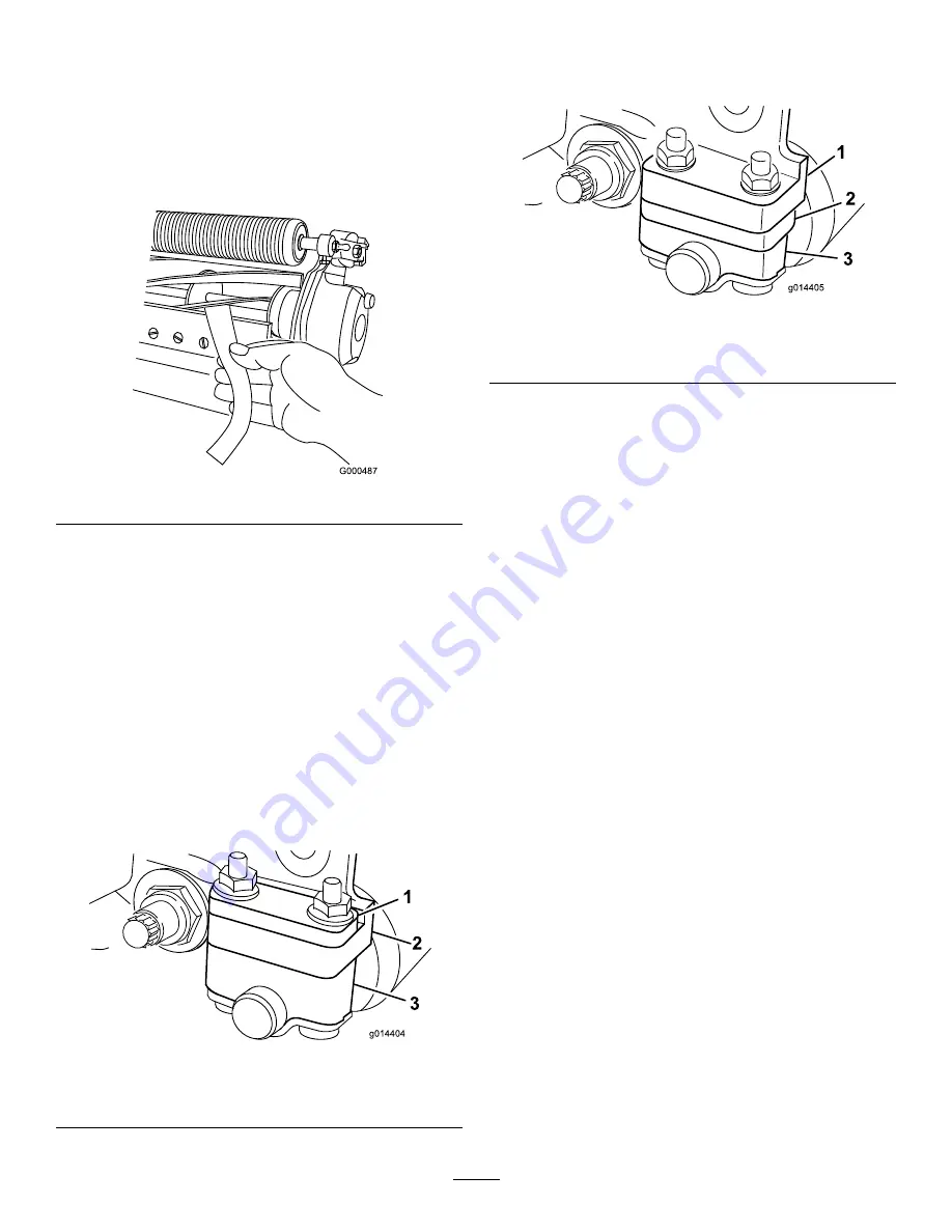
Test the cutting performance by inserting a long strip
of cutting performance paper (Toro part number
125-5610) between the reel and bedknife, perpendicular
to the bedknife (Figure 5). Slowly rotate the reel
forward; it should cut paper
Figure 5
Note:
If excessive contact/reel drag is evident it will
be either necessary to backlap, reface the front of the
bedknife, or regrind the cutting unit to achieve the
sharp edges needed for precision cutting (Refer to the
Toro Manual for Sharpening Reel and Rotary Mowers,
Form No. 09168SL).
Adjusting the Rear Roller
1.
Adjust the rear roller brackets (Figure 6 or Figure 7)
to the low or high position depending on the desired
height of cut range.
Position the spacer above the sideplate mounting flange
(factory setting) when height of cut settings range from
1.6 to 6 mm (1/16 to 1/4 inch) (Figure 6).
Figure 6
1.
Spacer
3.
Sideplate mounting flange
2.
Roller bracket
Position the spacer below the sideplate mounting
flange when height of cut settings range from 3 to 25
mm (1/8 to 1 inch) (Figure 7).
Figure 7
1.
Spacer
3.
Sideplate mounting flange
2.
Roller bracket
2.
To adjust rear roller proceed as follows:
A.
Raise the rear of the cutting unit and place a block
under the bedknife.
B.
Remove the 2 nuts securing each roller bracket
and spacer to each sideplate mounting flange.
C.
Lower the roller and screws from the sideplate
mounting flanges and spacers.
D.
Place the spacers onto the screws on the roller
brackets.
E.
Secure the roller bracket and spacers to the
underside of the mounting flanges with the nuts
previously removed.
Note:
The position of the rear roller to the reel
is controlled by the machining tolerances of the
assembled components and paralleling is not required.
Adjusting the Height of Cut
Note:
For heights of cut greater than 1.270 cm (0.500 inch),
you must install the high height of cut kit.
Important:
Whenever the cutting unit has to be tipped
to expose the bedknife/reel, prop up the rear of the
cutting unit to make sure the nuts on the back end of
the bedbar adjusting screws are not resting on the work
surface (Figure 3).
1.
Loosen the locknuts securing the height-of-cut arms to
the cutting unit side plates (Figure 8).
5


