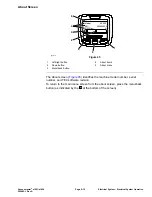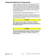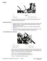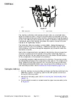
Throttle Potentiometer and Clutch Bail Potentiometer
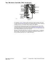
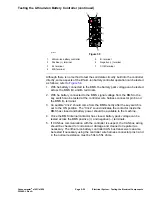
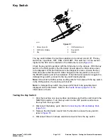
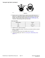
g337125
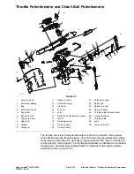
Figure 59
1.
Screw (4 each)
11.
Spacer (2 each)
21.
Extension spring
2.
InfoCenter display
12.
Control bail lever
22.
Spring tab
3.
Key
13.
Clevis pin
23.
Spacer (2 each)
4.
InfoCenter mount
14.
Lock nut
24.
Screw (2 each)
5.
Key switch
15.
Lock
25.
Throttle potentiometer sensor
6.
Bail catch fork
16.
Clutch bail potentiometer sensor
26.
Control bail lever
7.
Clip pin (2 each)
17.
Mount
27.
Throttle cable
8.
Link shaft
18.
Proximity sensor
28.
Lock
9.
Washer
19.
Screw (2 each)
29.
Lock nut (2 each)
10.
Clevis pin
20.
Screw (2 each)
The throttle and clutch bail potentiometers controls the electric motor speed
which determines the traction speed. The TEC uses the potentiometers setting
as an input to determine the necessary signal output for the motor controller for
correct electric motor speed. The throttle potentiometer is attached to the bottom
handle cover and clutch bail potentiometer is attached to the upper receiver
weldment; refer to (
).
Greensmaster
®
e1021/e1026
Page 5–33
Electrical System: Testing the Electrical Components
20246SL Rev A
Summary of Contents for 04831
Page 4: ...NOTES NOTES Page 4 Greensmaster e1021 e1026 20246SL Rev A ...
Page 6: ...g340650 Figure 1 Model 04831 shown Preface Page 6 Greensmaster e1021 e1026 20246SL Rev A ...
Page 14: ...Safety Safety and Instructional Decals Page 1 6 Greensmaster e1021 e1026 20246SL Rev A ...
Page 136: ...Electrical System Service and Repairs Page 5 56 Greensmaster e1021 e1026 20246SL Rev A ...
Page 216: ......

