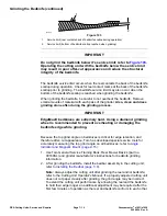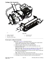
Servicing the Bedbar Adjuster
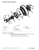
Removing the Bedbar Adjuster
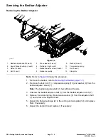
g261412
Figure 99
1.
Bedbar adjuster shaft (2 each)
5.
Wave washer (2 each)
9.
Washer (2 each)
2.
Keyed flanged bushing (4 each)
6.
Retaining ring (2 each)
10.
Compression spring
3.
Detent (2 each)
7.
Bedbar adjuster screw (2 each)
11.
Nut (2 each)
4.
Bolt (2 each)
8.
Bedbar assembly
12.
Side plate
Note:
Refer to
during this procedure.
1.
Remove the bedbar; refer to
Removing the Bedbar (page 7–7)
.
2.
Remove the lock nut (11), compression spring (10) and washer (9) from the
bedbar adjuster screw (7).
Note:
The bedbar adjuster shaft (1) has left-hand threads.
3. Unscrew the bedbar adjuster shaft (1) from the bedbar adjuster screw (7).
4. Remove the retaining ring (6) and wave washer (5) from the adjuster shaft
(7) and remove the adjuster shaft.
5. Inspect the flange bushings (2) in the cutting unit side plate (12) and replace
them if necessary.
6. Inspect the detent (3) and replace it if necessary.
DPA Cutting Units: Service and Repairs
Page 7–10
Greensmaster
®
e1021/e1026
20246SL Rev A
Summary of Contents for 04831
Page 4: ...NOTES NOTES Page 4 Greensmaster e1021 e1026 20246SL Rev A ...
Page 6: ...g340650 Figure 1 Model 04831 shown Preface Page 6 Greensmaster e1021 e1026 20246SL Rev A ...
Page 14: ...Safety Safety and Instructional Decals Page 1 6 Greensmaster e1021 e1026 20246SL Rev A ...
Page 136: ...Electrical System Service and Repairs Page 5 56 Greensmaster e1021 e1026 20246SL Rev A ...
Page 216: ......

