Chapter 5
Electrical System
Table of Contents
Operator's Manual.............................................................................................................................. 5–2
Electrical Schematics and Diagrams.................................................................................................. 5–2
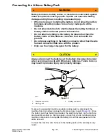
Connecting the Lithium Battery Pack ................................................................................................. 5–3
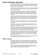
Battery Charging ................................................................................................................................ 5–4
Start Process ..................................................................................................................................... 5–5
Run Process ...................................................................................................................................... 5–5
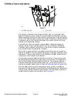
CAN-bus Communications................................................................................................................. 5–6
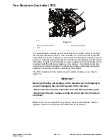
Toro Electronic Controller (TEC) ........................................................................................................ 5–7
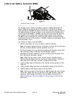
Lithium-Ion Battery Controller (BMS) ................................................................................................. 5–8
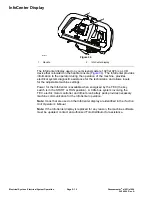
InfoCenter Display ........................................................................................................................... 5–10
Fuses ............................................................................................................................................... 5–22
CAN bus........................................................................................................................................... 5–24
Toro Electronic Controller (TEC) ...................................................................................................... 5–26
Lithium-Ion Battery Controller (BMS) ............................................................................................... 5–28
Electric Motor ................................................................................................................................... 5–30
Key Switch ....................................................................................................................................... 5–31
Throttle Potentiometer and Clutch Bail Potentiometer...................................................................... 5–33
Main Contactor................................................................................................................................. 5–36
CAN-bus Terminator Resistor .......................................................................................................... 5–39
Relay................................................................................................................................................ 5–40
Electric Motor ................................................................................................................................... 5–42
Servicing the Electric Motor ............................................................................................................. 5–44
Lithium-Ion Battery Controller (BMS) ............................................................................................... 5–47
Lithium-Ion Battery Pack .................................................................................................................. 5–50
Greensmaster
®
e1021/e1026
Page 5–1
Electrical System
20246SL Rev A
Summary of Contents for 04831
Page 4: ...NOTES NOTES Page 4 Greensmaster e1021 e1026 20246SL Rev A ...
Page 6: ...g340650 Figure 1 Model 04831 shown Preface Page 6 Greensmaster e1021 e1026 20246SL Rev A ...
Page 14: ...Safety Safety and Instructional Decals Page 1 6 Greensmaster e1021 e1026 20246SL Rev A ...
Page 136: ...Electrical System Service and Repairs Page 5 56 Greensmaster e1021 e1026 20246SL Rev A ...
Page 216: ......

