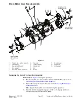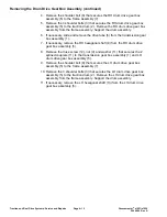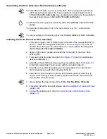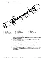
Disassembling the Transmission Gear Box Assembly (continued)
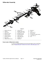
9. If necessary, disassemble the differential assembly (14); refer to
Disassembling the Differential Assembly (page 4–33)
.
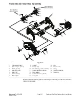
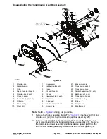
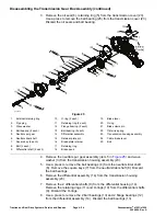
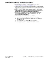
10. Remove the bolt (25) that secures the cable brake lever (24) onto the brake
lever (19). Slide and remove the cable brake lever (24) and external retaining
ring (1) from the brake lever (19).
11. Remove the 2 bolts (8) that secures the retainer plate pin (15) and brake
plate retainer (16) to the transmission housing assembly (23). Remove the
retainer plate (15) from the transmission housing assembly (23).
12. Slide and remove the brake lever assembly (19) from the transmission
housing assembly (23). Remove the flat wire spring (22) from the
transmission housing assembly (23).
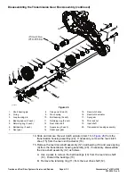
13. Disassemble the brake lever assembly (19) as follows:
A. Remove the retaining ring (17) from the brake clevis pin (21).
B. Slide and remove the brake clevis pin (21) from the brake band (18)
and brake lever (19).
C. Remove the brake lever (19) from the brake band (18).
D. Remove and discard the O-ring (20) from the brake lever (19).
Greensmaster
®
e1021/e1026
Page 4–25
Traction and Reel Drive Systems: Service and Repairs
20246SL Rev A
Summary of Contents for 04831
Page 4: ...NOTES NOTES Page 4 Greensmaster e1021 e1026 20246SL Rev A ...
Page 6: ...g340650 Figure 1 Model 04831 shown Preface Page 6 Greensmaster e1021 e1026 20246SL Rev A ...
Page 14: ...Safety Safety and Instructional Decals Page 1 6 Greensmaster e1021 e1026 20246SL Rev A ...
Page 136: ...Electrical System Service and Repairs Page 5 56 Greensmaster e1021 e1026 20246SL Rev A ...
Page 216: ......

