background image

10

2.

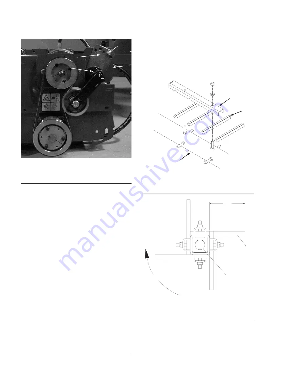
On back side of frame, loosen capscrew securing belt

tensioner to frame (Fig. 9).

1

2

3

4

Figure 9

1. Tensioner guide
2. Capscrew & nut

3. Capscrew (back of frame)
4. Tensioner

3.

Remove capscrew and nut securing tensioner guide to

drive mount (Fig. 9). Belt tension will be released when

capscrew is removed.

4.

Position a large wrench on tensioner. Rotate tensioner

clockwise until decal is aligned with 15

_

 on tensioner

tube.

5.

Insert capscrew into aligned guide holes and secure

with nut. If holes are not exactly aligned, rotate guide to

the next higher hole until aligned.

6.

Tighten capscrew, on back side of frame to lock

tensioner.

7.

Install the motor shield with the fasteners previously

removed.

Replacing Finger Belts

1.

Loosen nuts and washers securing finger pinchers to

rotor (Fig. 10 & 11).

2.

Remove old belt fingers.

3.

Install new belt fingers. Belt fingers to extend from

finger pinchers approximately 4 inches (Fig. 10 & 11).

4.

Tighten nuts securing assembly.

1

3

2

Figure 10

1. Finger pincher
2. Rotor

3. Belt finger

1

2

3

4

Figure 11

1. 3.63 inches
2. Flat side of belt

3. Keyed shaft
4. Brush rotation

Summary of Contents for 07081

Page 1: ...Operator s Manual English EN Form No 3350 959 Rev C Finger Deck Versa Vac Model No 07081 Serial No 240000001 and Up...

Page 2: ...enever you need service genuine Toro parts or additional information contact an Authorized Service Dealer or Toro Customer Service and have the model and serial numbers of your product ready Write the...

Page 3: ...ylight or when there is good artificial light Drive slowly and watch for holes or other hidden hazards Do not drive close to a sand trap ditch creek or other hazard Reduce your speed when making sharp...

Page 4: ...y area of potential danger Replace any decal that is damaged or lost 105 4586 1 Entanglement hazard belt stay away from moving parts Do not operate the machine with the shields or guards removed keep...

Page 5: ...als Four pneumatic 4 1 4 NHS 2 ply tires Finger Rotor One piece welded base weldment 1 inch diameter shaft inside of a 2 in square tube with 3 16 wall 88 rubber fingers 6 in long Operates 1100 rpm 100...

Page 6: ...th a washer and hair pin cotter Fig 1 1 Figure 1 1 Tow arm 3 Connect each lift chain to a deck bracket with a clevis pin and hair pin cotter Fig 2 1 Figure 2 1 Lift chain 4 Install canvas ring around...

Page 7: ...ing Height 1 Remove the clevis pin from the spindle shaft Fig 5 1 2 2 3 Figure 5 1 Clevis pin 2 Spacer 3 Caster arm 2 Remove or add C shaped spacers to the spindle shaft below the castor arm to get th...

Page 8: ...will pick up twigs clippings leaves pine needles and pine cones and small debris Important Do not make sharp turns when using the finger deck as damage to turf may occur Important Do not operate fing...

Page 9: ...tant Lubricating the deck immediately after washing helps purge water out of the bearings and increases bearing life 1 Wipe each grease fitting with a clean rag 2 Wipe excess grease away Figure 6 Figu...

Page 10: ...gned guide holes and secure with nut If holes are not exactly aligned rotate guide to the next higher hole until aligned 6 Tighten capscrew on back side of frame to lock tensioner 7 Install the motor...

Page 11: ...11...

Page 12: ...is not limited to dam age to seats due to wear or abrasion worn painted surfaces scratched decals or windows etc Parts Parts scheduled for replacement as required maintenance are war ranted for the p...

Reviews: