Checking the Cooling System
Service Interval:
Before each use or daily
Cooling system capacity:
4 qt (3.7 l)
The cooling system is filled with a 50/50 solution of
water and permanent ethylene glycol antifreeze.
1. Park the machine on a level surface.
CAUTION
If the engine has been running, the pressurized,
hot coolant can escape and cause burns.
•
Do not open the radiator cap when the
engine is running.
•
Allow the engine to cool at least 15 minutes
or until the radiator cap is cool enough to
touch without burning your hand.
•
Use a rag when opening the radiator cap,
and open the cap slowly to allow steam to
escape.
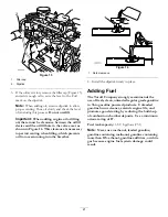
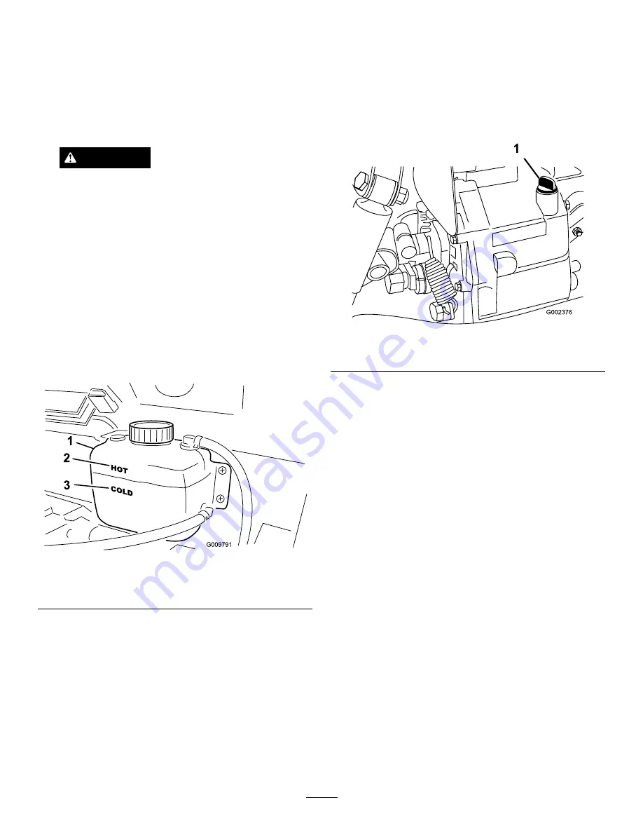
2. Check the coolant level on the side of the reserve
tank (Figure 18). The coolant should be up to the
Cold line, when engine is cold.
Figure 18
1.
Reserve tank
3.
Cold line
2.
Hot line
3. If coolant is low, remove the reserve tank cap
and add a 50/50 mixture of water and permanent
ethylene glycol antifreeze.
Do not overfill.
4. Install the reserve tank cap.
Checking the
Transaxle/Hydraulic Fluid
Level
Service Interval:
Before each use or daily
The transaxle reservoir is filled with Dexron III ATF.
Check the level before the engine is first started and
every 8 hours or daily, thereafter. Capacity of system is .
Transaxle reservoir capacity:
7.5 qt (7 l).
1. Position the vehicle on a level surface.
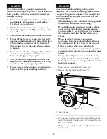
2. Clean the area around the dipstick (Figure 19).
Figure 19
1.
Dipstick
3. Unscrew the dipstick from the top of the transaxle
and wipe it with a clean rag.
4. Screw the dipstick into the transaxle and ensure that
it is fully seated.
5. Unscrew the dipstick and check the fluid level.
The fluid should be up to top of the flat portion
of the dipstick.
6. If the level is low, add enough fluid to achieve the
proper level.
Checking the High Flow
Hydraulic Fluid (TC models
only)
Service Interval:
Before each use or daily
The high flow hydraulics reservoir is filled with
approximately 4 US gallons (15 l) of high quality
hydraulic fluid.
Check the level of hydraulic
fluid before the engine is first started and daily
thereafter.
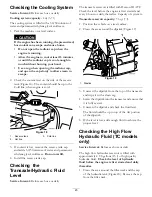
1. Clean the area around the filler neck and the cap
of the hydraulic tank (Figure 20). Remove the cap
from the filler neck.
23
Summary of Contents for 07367TC
Page 41: ...Figure 44 41...
Page 60: ...Schematics Hydraulic Schematic Rev B High Flow Hydraulics Schematic TC models only Rev A 60...
Page 61: ...Electrical Schematic Rev B 61...
Page 62: ...Notes 62...
Page 63: ...Notes 63...


