background image

Make sure all hydraulic line connectors are tight, and
all hydraulic hoses and lines are in good condition
before applying pressure to the system.

Keep your body and hands away from pin hole
leaks or nozzles that eject hydraulic fluid under
high pressure. Use paper or cardboard, not hands,
to search for leaks. Hydraulic fluid escaping under
pressure can have sufficient force to penetrate skin
and do serious damage. If fluid is injected into the
skin it must be surgically removed within a few
hours by a doctor familiar with this form of injury
or gangrene may result.

Before disconnecting or performing any work on the
hydraulic system, all pressure in the system must be
relieved by stopping the engine, cycling the dump
valve from raise to lower and/or lowering box and
attachments. Place the remote hydraulics lever in the
float position. If the box must be in raised position,
secure it with the safety support.

To make sure the entire machine is in good condition,
keep all nuts, bolts, and screws properly tightened.

To reduce the potential fire hazard, keep the engine
area free of excessive grease, grass, leaves, and
accumulation of dirt.

If the engine must be running to perform a
maintenance adjustment, keep hands, feet, clothing,
and any parts of the body away from the engine and
any moving parts. Keep everyone away.

Do not overspeed the engine by changing the
governor settings. The maximum engine speed is
3650 RPM. To ensure safety and accuracy, have an
Authorized Toro Distributor check the maximum
engine speed with a tachometer.

If major repairs are ever needed or assistance is
required, contact an Authorized Toro Distributor.

To be sure of optimum performance and safety,
always purchase genuine Toro replacement parts and
accessories. Replacement parts and accessories made
by other manufacturers could be dangerous. Altering
this vehicle in any manner may affect the vehicle’s
operation, performance, durability or its use may
result in injury or death. Such use could void the
product warranty of The Toro® Company.

This vehicle should not be modified without
The Toro® Company’s authorization. Direct any
inquiries to The Toro® Company, Commercial
Division, Vehicle Engineering Dept., 8111 Lyndale
Ave. So., Bloomington, Minnesota 55420–1196.
USA

Sound Pressure

This unit has a sound pressure level at the operator’s
ear of 75 dBA, which includes an Uncertainty Value (K)
of 1 dBA.

The sound pressure level was determined according to
the procedures outlined in EN ISO 11201.

Vibration

Hand-Arm

Measured vibration level for right hand = 0.34 m/s

2

Measured vibration level for left hand = 0.43 m/s

2

Uncertainty Value (K) = 0.5 m/s

2

Measured values were determined according to the
procedures outlined in EN 1032.

Whole Body

Measured vibration level = 0.33 m/s

2

Uncertainty Value (K) = 0.5 m/s

2

Measured values were determined according to the
procedures outlined in EN 1032.

7

Summary of Contents for 07367TC

Page 1: ...No 07367 Serial No 310000001 and Up Model No 07367TC Serial No 310000001 and Up Model No 07370 Serial No 310000001 and Up Model No 07370TC Serial No 310000001 and Up To register your product or downl...

Page 2: ...o learn how to operate and maintain your product properly and to avoid injury and product damage You are responsible for operating the product properly and safely You may contact Toro directly at www...

Page 3: ...Transporting Vehicle 31 Towing the Vehicle 31 Towing a Trailer with the Vehicle 32 Hydraulic Control 32 Maintenance 34 Recommended Maintenance Schedule s 34 Service Interval Chart 35 Heavy Duty Opera...

Page 4: ...rs ADDRESS American National Standards Institute Inc 1430 Broadway New York New York 10018 U S A ANSI UL 558 Internal Combustion Engine Powered Industrial Trucks ADDRESS American National Standards In...

Page 5: ...ing the machine Always wear substantial shoes Do not operate the machine while wearing sandals tennis shoes or sneakers Do not wear loose fitting clothing or jewelry which could get caught in moving p...

Page 6: ...traveling in the same direction at intersections blind spots or at other dangerous locations When dumping do not let anyone stand behind vehicle and do not dump the load on any one s feet Release the...

Page 7: ...verspeed the engine by changing the governor settings The maximum engine speed is 3650 RPM To ensure safety and accuracy have an Authorized Toro Distributor check the maximum engine speed with a tacho...

Page 8: ...Manual 4 Warning read the Operator s Manual 115 2047 1 Warning do not touch the hot surface 115 7740 1 Warning maximum trailer weight is 1500 lb 680 kg maximum tongue weight is 200 lb 90 kg 2 Warning...

Page 9: ...n carrying a full or heavy load 115 2282 1 Warning read the Operator s Manual 2 Warning stay away from moving parts keep all guards and shields in place 3 Crushing dismemberment hazard of bystanders k...

Page 10: ...e protection explosive gases can cause blindness and other injuries 3 Caustic liquid chemical burn hazard 8 Battery acid can cause blindness or severe burns 4 Wear eye protection 9 Flush eyes immediat...

Page 11: ...9 Entanglement hazard shaft keep bystander s a safe distance from the vehicle 3 Unlocked 10 Retract hydraulics 4 Hydraulic lock 11 Extend hydraulics 5 Engage 12 Transmission high speed 6 Power take o...

Page 12: ...orn 5 Engine start 3 Engine stop 106 7767 1 Warning read the Operator s Manual avoid tipping the machine wear the seat belt lean away from the direction the machine is tipping 93 9899 93 9899 1 Crushi...

Page 13: ...nual 1 Read before operating the vehicle Parts Manual 1 Use to reference part numbers Operator Training Material 1 View before operating machine Note Determine the left and right side of the machine f...

Page 14: ...the vehicle filled with electrolyte and charged Bulk electrolyte with 1 260 specific gravity can be purchased from a local battery supply outlet WARNING CALIFORNIA Proposition 65 Warning Battery posts...

Page 15: ...tery terminals are toward the outside of the vehicle 8 Install the positive cable red to the positive terminal and the negative cable black to the negative terminal of the battery and secure then with...

Page 16: ...p or slow vehicle CAUTION Worn or maladjusted brakes may result in personal injury If the brake pedal travels to within 1 1 2 inches 3 8 cm of the vehicle floor board the brakes must be adjusted or re...

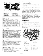
Page 17: ...ge Shifter The high low range shifter adds three additional speeds for precise speed control Figure 9 The vehicle must be completely stopped before shifting between High and Low range Shift only on le...

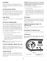
Page 18: ...inutes for the light to come on Coolant Temperature Gauge and Light Registers the coolant temperature in the engine Operates only when the ignition switch is in On position Figure 10 The indicator lig...

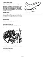
Page 19: ...ter Registers the ground speed of the vehicle Figure 10 The speedometer is in MPH but can easily converted to KPH Refer to Converting the Speedometer in Controls Maintenance Power Point Use the power...

Page 20: ...sides of the machine from the normal operating position CAUTION Before servicing or making adjustments to the machine stop the engine set the parking brake and remove the key from the switch Remove a...

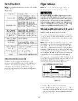
Page 21: ...y to permit venting when filling which prevents oil from overrunning into the breather Figure 16 1 Note clearance 4 Install the dipstick firmly in place Adding Fuel The Toro Company strongly recommend...

Page 22: ...ring fueling static electricity can be released causing a spark which can ignite the gasoline vapors A fire or explosion from gasoline can burn you and others and can damage property Always place gaso...

Page 23: ...g the Transaxle Hydraulic Fluid Level Service Interval Before each use or daily The transaxle reservoir is filled with Dexron III ATF Check the level before the engine is first started and every 8 hou...

Page 24: ...pressure hydraulic fluid Use cardboard or paper to find hydraulic leaks Safely relieve all pressure in the hydraulic system before performing any work on the hydraulic system Seek immediate medical a...

Page 25: ...ever comes first Change the brake fluid The brake fluid reservoir is shipped from the factory filled with DOT 3 brake fluid Check the level before the engine is first started and every 8 hours or dail...

Page 26: ...arter longer than 15 seconds After 15 seconds of continuous cranking wait 60 seconds before engaging starter motor again Driving the Vehicle 1 Release the parking brake 2 Fully press the clutch pedal...

Page 27: ...s there is a malfunction in the interlock system that must be repaired before operating the vehicle Verifying the Hydraulic Lift Lever Interlock Switch 1 Sit on the operator s seat and engage the park...

Page 28: ...reas If you must drive when it is dark be sure to drive cautiously use the head lights and even consider adding additional lights Passengers Whenever you have a passenger riding in the vehicle make su...

Page 29: ...This will dry the brakes out Do not downshift for braking on icy or slippery surfaces wet grass or while going down a hill because engine braking may cause skidding and loss of control Shift to a low...

Page 30: ...cks fertilizer or landscape timbers stack higher in the box The height and weight of the load has a significant influence on tip overs The higher a load is stacked the more likely the vehicle is to ti...

Page 31: ...similar to that of a two wheel drive vehicle The four wheel drive system functions in both froward and reverse however when turning the rear wheels will slip slightly more before power is delivered t...

Page 32: ...whenever the engine is running The power can be used through the quick couplers at the rear of the vehicle Important If multiple vehicles use the same attachment cross contamination of the transmissi...

Page 33: ...necting the Quick Couplers Important Clean dirt from quick couplers before connecting Dirty couplers can introduce contamination into the hydraulic system 1 Pull back the locking ring on the coupler 2...

Page 34: ...k condition and tension of the alternator belt After the first 10 hours Torque the front and rear wheel nuts Check the adjustment of the shift cables Check the adjustment of the parking brake Replace...

Page 35: ...on and tension of the alternator belt Check the adjustment of the clutch pedal Inspect the service and parking brakes Every 400 hours Inspect or replace the spark plugs Replace the fuel filter Check t...

Page 36: ...cautions must be taken or serious injury or death could result WARNING Before servicing or making adjustments to the machine stop engine set parking brake and remove key from the ignition switch Remov...

Page 37: ...ns securing the cylinder rod ends to the bed mounting plates by pushing the pins towards the inside Figure 34 4 Remove the lynch pins and clevis pins securing the pivot brackets to the frame channels...

Page 38: ...with a bolt and nut to prevent assembly errors 4 Start the engine and engage the hydraulic lift lever to raise the bed Release the lift lever and turn off the engine Install the bed safety support to...

Page 39: ...m of the hood upward until the top mounting tabs can be pulled from the frame slots Figure 39 3 Pivot the top of hood forward and unplug the wire connectors from the head lights Figure 39 4 Remove the...

Page 40: ...ivot mounts 2 and steering cylinder 2 Figure 40 Spring tower 2 Figure 41 Clutch 1 accelerator 1 brake 1 Figure 42 Accelerator arm 1 Figure 43 U joint 18 and 4 wheel drive shaft 3 Figure 44 Important W...

Page 41: ...Figure 44 41...

Page 42: ...e large accumulations of debris packed between the outside of the primary filter and the canister Important Avoid using high pressure air which could force dirt through the filter into the intake trac...

Page 43: ...e and reduce exhaust emission level The correct spark plug to use is a Champion RC 14YC or NGK BPR 4ES The recommended air gap is 0 032 inch 0 81 mm 1 Clean the area around the spark plugs so foreign...

Page 44: ...the fuel pump assembly and fuel filter from the tank Figure 50 6 Remove the clamp securing the fuel filter hose to the fuel pump fitting Remove the hose from the fitting Figure 50 7 Insert the new hos...

Page 45: ...ehicle Be sure your vehicle is not touching the jump start vehicle Connecting cables to the wrong post could result in personal injury and or damage to the electrical system 1 Squeeze the battery cove...

Page 46: ...d your eyes and rubber gloves to protect your hands Fill the battery where clean water is always available for flushing the skin Keep battery electrolyte level properly maintained Keep the top of the...

Page 47: ...lamp Contact your Authorized Toro Distributor for repair if you find any damage Adjusting the Shift Cables Service Interval After the first 10 hours Every 200 hours 1 Move shift lever to the Neutral p...

Page 48: ...n example of tire wear caused by under inflation Figure 58 1 Under inflated tire Figure 59 is an example of tire wear caused by over inflation Figure 59 1 Over inflated tire Checking the Front Wheel A...

Page 49: ...ance Removing Debris from the Cooling System Service Interval Before each use or daily Clean more frequently in dirty conditions 1 Turn the engine off Clean the engine area thoroughly of all debris 2...

Page 50: ...cap 5 Disconnect the lower radiator hose and allow coolant to flow into a drain pan When coolant stops connect the lower radiator hose 6 Open the bleed screw on top of the water pump Figure 66 Figure...

Page 51: ...en repeat step 3 5 Install the rubber grip onto the parking brake lever Adjusting the Brake Pedal Service Interval Every 200 hours Note Remove the font hoot to ease the adjustment procedure 1 Remove t...

Page 52: ...eck the tension by pressing the belt at mid span between the crankshaft and alternator pulleys with 22 lb 10 kg of force A new belt should deflect 0 3 to 0 5 inch 8 to 12 mm A used belt should deflect...

Page 53: ...orized Toro Dealer Distributor for assistance Figure 72 1 Accelerator cable 2 Ball joint Figure 73 1 0 200 to 0 350 inch 5 to 8 9 mm clearance Adjusting the Clutch Pedal Service Interval Every 200 hou...

Page 54: ...to the clutch pedal after the jam nut is tightened Figure 76 Figure 76 1 Clutch cable rod end 3 Rod end jam nut 2 Clutch pedal 4 Parallel Note The clutch free play should never be less than 0 75 inch...

Page 55: ...o air dry before installing Figure 78 1 Hydraulic strainer 5 Install the strainer 6 Install the hydraulic hose and 90 degree fitting to the strainer in the same orientation 7 Install and tighten the d...

Page 56: ...2270 140 to 152 Pour Point ASTM D97 35 F to 46 F FZG Fail stage 11 or better Water content new fluid 500 ppm maximum Industry Specifications Vickers I 286 S Vickers M 2950 S Denison HF 0 Vickers 35 VQ...

Page 57: ...portant The vehicles hydraulic system uses Dexron III ATF To avoid system contamination make sure the vehicle used to jump the hydraulic system uses an equivalent fluid 2 On both vehicles disconnect t...

Page 58: ...ry 3 Inspect the brakes refer to Inspecting the Brakes 4 Service the air cleaner refer to Servicing the Air Cleaner 5 Grease the machine 6 Change the engine oil refer to Changing the Engine Oil and Fi...

Page 59: ...e Do not connect the battery cables to the battery posts during storage Important The battery must be fully charged to prevent it from freezing and being damaged at temperatures below 32 F 0 C A fully...

Page 60: ...Schematics Hydraulic Schematic Rev B High Flow Hydraulics Schematic TC models only Rev A 60...

Page 61: ...Electrical Schematic Rev B 61...

Page 62: ...Notes 62...

Page 63: ...Notes 63...

Page 64: ...ainted surfaces scratched decals or windows etc Parts Parts scheduled for replacement as required maintenance are warranted for the period of time up to the scheduled replacement time for that part Pa...

Reviews: