background image

E

1999 

The Toro Company

8111 Lyndale Ave. South
Bloomington, MN  55420–1196

All Rights Reserved

Printed in the USA

Form No. 3322-861

Model 100-2863

Kawasaki Zone Start Engine Coversion Kit

For Toro Walk Power Lawn Mowers

Installation

Instructions

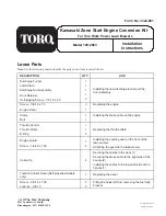
Loose Parts

Note: Use the following chart to identify the parts you will use to install the kit.

DESCRIPTION

QTY.

USE

Discharge Tunnel

Latch Plate

Discharge Door Assembly

Door Retainer

Self-tapping Screw – 1/4-10 x .60

1

1

1

1

2

Installing the new discharge tunnel and the
door assembly

Screw – 3/8-16 x 1.5

3

Replacing the engine

Engine Decal

1

Clamp

1

Installing the brake cable on the engine

Bolt

1

Throttle Control

Throttle Cable

E-Ring

1

1

2

Replacing the throttle cable

Engine Guard

Screw – 1/4-20 x 1.00

1

4

Installing the engine guard on the front of the
lawn mower

Attaching the guard to the lawn mower

Cable Tie

4

Securing the cables to the deck (1)

Securing the brake cable to the right side of the
handle (2)

Installing the cables to the lower left side of the
handle (1)

Traction Control Decal (Self-propelled models
only)

1

Replacing the decal

Screw – 3/8-16 x 1.00

Locknut – 3/8-16

2

2

Filling the holes left from removing the fuel tank
bracket

Summary of Contents for 100-2863

Page 1: ...rge tunnel and the door assembly Screw 3 8 16 x 1 5 3 Replacing the engine Engine Decal 1 Clamp 1 Installing the brake cable on the engine Bolt 1 Throttle Control Throttle Cable E Ring 1 1 2 Replacing...

Page 2: ...plug POTENTIAL HAZARD If gasoline is spilled on a hot engine it could ignite WHAT CAN HAPPEN Contact with burning gasoline could cause serious personal injury HOW TO AVOID THE HAZARD Drain the gasolin...

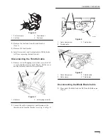
Page 3: ...ews that secure the belt cover to the lawn mower deck Fig 3 Set the cover and the fasteners aside for the installation m 224 2 1 2 Figure 3 1 Belt cover 2 Self tapping screw 2 2 Loosen the cable clamp...

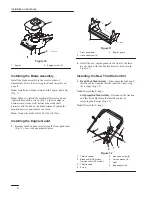
Page 4: ...de Assembly 1 Remove the blade bolt the lock washer the blade stiffener accelerator the blade the blade retainer the spacer and the square key and the crankshaft protector Fig 7 1 2 3 4 5 6 7 8 9 10 1...

Page 5: ...n the discharge tunnel with the holes in the lawn mower deck 2 Fasten the rear left and the rear right corners of the discharge tunnel to the lawn mower deck using two capscrews two flat washers and t...

Page 6: ...Remove four hex head screws from the front quadrants Fig 11 Leave the quadrants in place m 4678 1 2 3 Figure 11 1 Front quadrants 2 Hex head screw 4 3 Engine guard 2 Install the new engine guard on t...

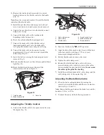
Page 7: ...ssion as shown in Figure 13 2 1 3 Figure 13 1 Throttle cable 2 Blade brake cable 3 Cable tie Adjusting the Throttle Control 1 Connect the throttle cable to the speed control lever on the engine Fig 14...

Page 8: ...6 1 2 4 3 Figure 16 Self propelled Model 1 Handle 2 Brake lever 3 3 16 in to 1 4 in 4 Cable bracket E Pull down on the cable conduit until there is no slack in the wire F Tighten the nut G Secure the...

Reviews: