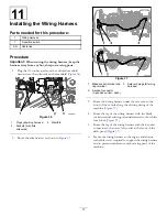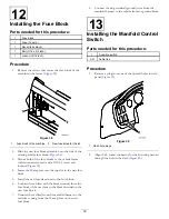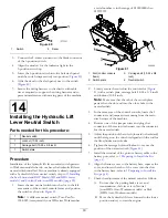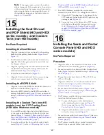
Removing the Quick Disconnect
Bracket
1.
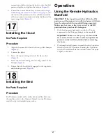
Remove the 2 flanged head bolts and 2 flanged locknuts
that secure the quick disconnect bracket to the flange
of the transmission support of the machine (
)
Note:
Retain the flanged head bolt and flanged
locknut for installation of the manifold bracket in
Installing the Manifold Bracket and Hydraulic Control
Manifold (page 12)
.
Figure 17
1.
Flanged head bolt
3.
Flanged head nut
2.
Quick disconnect bracket
2.
Remove the bracket from the machine (
).
3.
Remove the straight fittings and the quick disconnect
coupling from the quick disconnect bracket.
Note:
Retain the male and female quick disconnect
couplings and straight fittings; discard the bracket.
7
Preparing the Hydraulic
Control Manifold
Parts needed for this procedure:
1
Hydraulic control manifold
1
Straight hydraulic fitting (11/16 x 9/16 x 3/8 inch)
1
45° hydraulic fitting
3
90° hydraulic fitting
2
Straight hydraulic fittings (9/16 x 9/16 x 3/8 inch)
Preparing the Hydraulic Control
Manifold (non-HDX-Auto Workman
models)
Note:
Ensure that the O-rings are installed on the fittings
and lubricated with hydraulic fluid from the machine before
installing the fittings into the manifold.
1.
Install the A and B port fittings into the manifold as
follows:
•
For 2000 and 3000 series Workman
Install the 2 straight hydraulic fitting that you
removed in step
of
Disconnect Bracket (page 10)
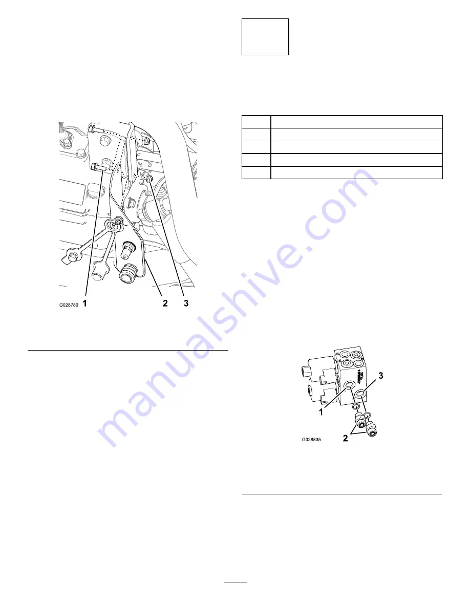
into ports A and B
of the maniflod (
Figure 18
1.
Port B (hydraulic control
manifold)
3.
Port A (hydraulic control
manifold)
2.
Straight hydraulic fitting
•
For HD, HDX, and HDX-D Workman
A.
Install 1 of the straight hydraulic fittings that
you removed in step
of
Disconnect Bracket (page 10)
into port B of
the hydraulic control manifold (
).
10


