background image

Safety

Safety and Instructional Decals

Safety decals and instructions are easily visible to the operator and are located near any area of potential
danger. Replace any decal that is damaged or lost.

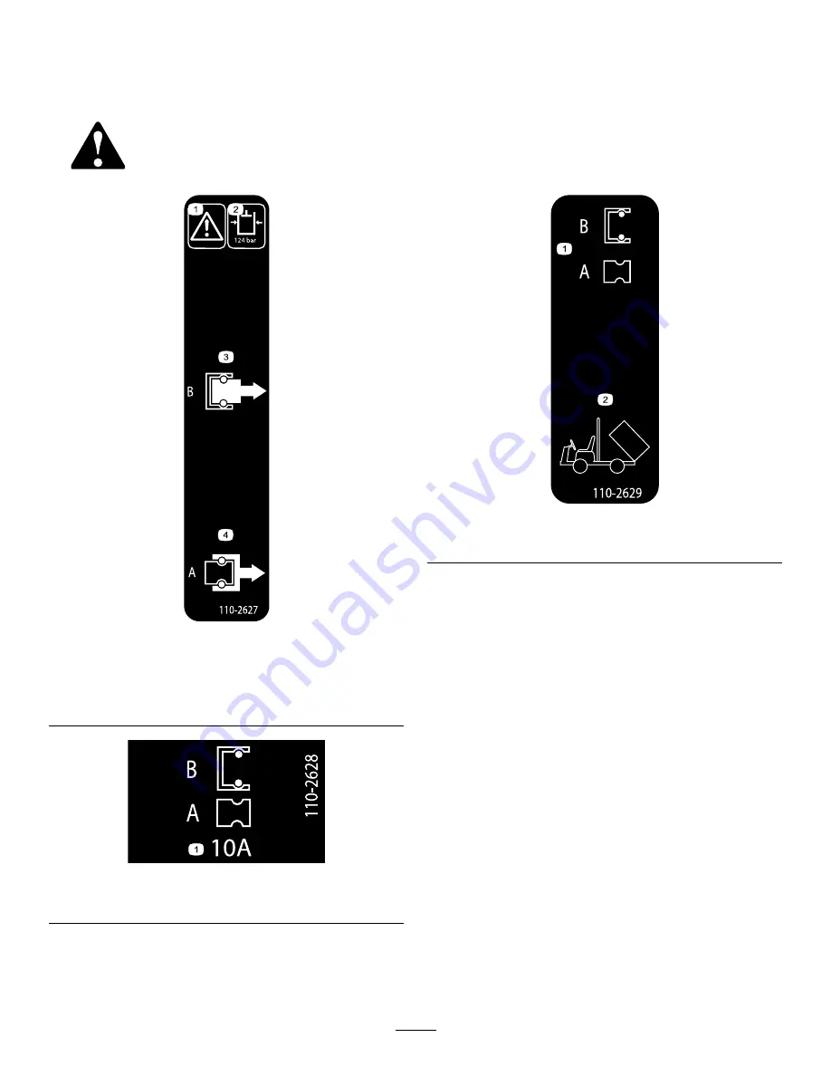
110-2627

1.

Warning

3.

Flow direction—when the
lift lever is in the B position

2.

Hydraulic oil
pressure—124 bar

4.

Flow direction—when the
lift lever is in the A position

110-2628

1.

Hydraulic manifold fuse block—10A fuse

110-2629

1.

Remote hydraulics

2.

Bed tilt

2


Summary of Contents for 110-2626

Page 1: ...CALIFORNIA Proposition 65 Warning This product contains a chemical or chemicals known to the State of California to cause cancer birth defects or reproductive harm 2015 The Toro Company 8111 Lyndale...

Page 2: ...y area of potential danger Replace any decal that is damaged or lost 110 2627 1 Warning 3 Flow direction when the lift lever is in the B position 2 Hydraulic oil pressure 124 bar 4 Flow direction when...

Page 3: ...9 16 x 9 16 x 3 8 inch 2 Prepare the hydraulic control manifold Flat manifold bracket 1 Flanged manifold bracket HDX Auto Workman models 1 Bolt 5 16 x 3 4 inch 2 8 Lock washer 5 16 inch 2 Install the...

Page 4: ...ne set the parking brake and remove the key from the key switch 3 Remove the bed from the machine refer to the Operator s Manual for your Workman model for the bed removal procedure 4 Disconnect the b...

Page 5: ...models No Parts Required Removing the Center Console Covers 1 Ensure that the parking brake is set 2 Remove the center console covers as follows For Workman models with an manual transmission A shift...

Page 6: ...ission remove the shift indicator as follow A Remove the 4 hex head screws that secure the shift indicator cover to the seat shroud Figure 7 Figure 7 Workman models with an Automatic Transmission 1 In...

Page 7: ...For HDX Auto Workman models remove the CVT cooling duct as follows A Remove the hose clamp that secures the CVT cooling duct to the flange of the CVT intake at the back of the ROPS panel on the passe...

Page 8: ...d to the male and female quick couplers at the quick disconnect bracket for the lift cylinders Removing the Hydraulic Lift Tubes HD HDX and HDX Auto series Workman 1 Disconnect the tube nuts for the e...

Page 9: ...nnect Hose Fittings 1 Align drain pan under the fittings at the quick disconnect bracket at the right rear of the machine Figure 16 Figure 16 1 Quick disconnect bracket 3 Quick disconnect fitting fema...

Page 10: ...c control manifold 1 Straight hydraulic fitting 11 16 x 9 16 x 3 8 inch 1 45 hydraulic fitting 3 90 hydraulic fitting 2 Straight hydraulic fittings 9 16 x 9 16 x 3 8 inch Preparing the Hydraulic Contr...

Page 11: ...the male quick disconnect coupling that you removed in step 3 of Removing the Quick Disconnect Bracket page 10 onto the straight hydraulic fittings 9 16 x 9 16 x 3 8 inch in port C3 Figure 21 5 Instal...

Page 12: ...sconnect coupling that you removed in step 3 of Removing the Quick Disconnect Bracket page 10 onto the straight hydraulic fittings 9 16 x 9 16 x 3 8 inch in port C4 Figure 24 8 Installing the Manifold...

Page 13: ...tain the bolts and nuts discard the old differential support 3 Align the holes in the new right differential support with the threaded holes in the differential Figure 27 Figure 27 1 Axle support 4 Di...

Page 14: ...draulic Lift Hoses 3000 and 4000 series Workman Connect the extend and retract hoses that you disconnected in Disconnecting the Hydraulic Lift Hoses 3000 and 4000 series Workman page 8 to the straight...

Page 15: ...the chassis with cable ties as required to support the hoses and prevent interference with moving parts of the machine Installing the Hoses HDX Auto Workman models 1 Install the straight fitting of th...

Page 16: ...ing parts of the machine 10 Connecting the Lift Cylinder Hoses to the Manifold No Parts Required Procedure 1 Connect the lift cylinder hose with the male quick disconnect coupling with the female quic...

Page 17: ...et terminal and ring terminal 3 Solenoid plugs kit wiring harness 2 8 socket connector 3 position switch dash 3 Route the wiring harness under the seat area to the front of the vehicle along the exist...

Page 18: ...into the top slot in the new fuse block 5 Install the new fuse decal next to the fuse block 6 Connect the red lead with the black terminal from the fuse block of the machine to the black terminal on t...

Page 19: ...serial number is in the range of 240000000 thru 249999999 Figure 41 1 Slot control console frame 3 Carriage bolt 10 24 x 5 8 inch 2 Switch plate 4 Neutral switch 2 Loosely secure the switch in the co...

Page 20: ...ntil the tank is firmly seated Figure 11 refer to 4 Removing the Coolant Tank non HD models ROPS Shield and Seat Shroud HD and HDX series models page 7 3 For HDX Workman models with an automatic trans...

Page 21: ...Required Procedure For Workman models with a utility bed install the bed onto the machine refer to the Operator s Manual for your Workman model for the bed installation procedure Operation Using the...

Page 22: ...Notes 22...

Page 23: ...Notes 23...

Page 24: ......

Reviews: