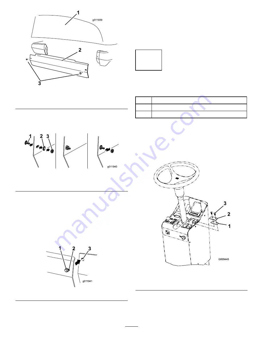
g01
1939
1
2
3
Figure 2
1.
Hood
3.
Screw (5/16 x 3/4 inch)
2.
Side panel
2. Install the screw (5/16 x 3/4 inch) to the side panel
and turn over to install the push nut onto the bolt
(Figure 3).
g01 1940
1
2 3
Figure 3
1.
Retained fastener
3.
Machine
2.
Side panel
3. Install the hex nut (5/16 inch) over the screw and
push nut (5/16 inch) and tighten to flatten the push
nut onto screw (Figure 3).
4. Remove the hex nut and repeat the action on to
flatten all remaining push nuts on the side panel.
Remove the hex nut when finished and discard.
Install the side panel with the retained fastener to
the machine (Figure 4).
1
2
3
g01 1941
Figure 4
Important:
The fasteners on the covers of this
machine are designed to remain on the cover
after removal. Loosen all of the fasteners on
each cover a few turns so that the cover is loose
but still attached, then go back and loosen them
until the cover comes free. This will prevent you
from accidentally stripping the bolts free of the
retainers.
3
Install the Speed Limiter
Parts needed for this procedure:
1
Spacer plate
1
Stop plate
2
Plastic plug
Procedure
1. Carefully puncture the decal material on the
console panel to expose the existing holes in front
of the engine speed selector and engine speed
increment/decrement switches (Figure 5).
Figure 5
1.
Spacer plate
3.
Plastic plugs
2.
Stop plate
2. Position the spacer plate onto the console panel so
the holes align with the holes in the console and the
back (straight) edge of the spacer plate aligns with
the switch base (Figure 5).
2


