background image

1

 2003 by The Toro Company

8111 Lyndale Avenue South
Bloomington, MN  55420-1196

Contact us at www.Toro.com

All Rights Reserved

Printed in Italy

13-32

Rear Engine Rider

Model Nos. 70185 and 70186

Form No. 3351-232

Setup Instructions

Loose Parts

Description

Qty.

Use

Wheels

Flat washers, M16 (3 mm thick)

Spacers, M16 (1 mm thick)

Cotter pins

2

2

4

2

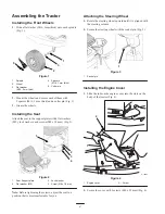
Installing the front wheels

Seat

Screws, M8 x 18 mm

Flat washers, M9

Lock washers

1

4

4

4

Installing the seat

Socket pin

1

Attaching the steering wheel

Engine cover

Screws, M6 x 25 mm

1

2

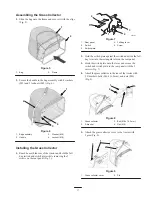
Installing the engine cover

Frame

Fabric bag with clips

Handle

Locknuts, M8

Washers, M9

1

1

1

2

4

Assembling the grass collector

Z-brackets

Bolts, M6 x 16.2 mm

Nuts, M6

Grass collector cover

Pins

Full bag lever

2

2

2

1

2

1

Installing the grass collector

Bolts, M6 x 20 mm

Flat washers, M6.5

Nuts, M6

2

4

2

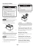
Installing the battery

Recycler

 cover

1

Recycling the grass clippings; refer to the tractor
Operator’s Manual

Draining tube

1

Draining the engine oil

Keys

2

Using the keys in ignition and KeyChoice

 switches

Spark plug wrench

1

Replacing the spark plug

Operator’s Manuals (English and French)

Engine operator’s manual

2

1

Reading before operating the tractor

Summary of Contents for 13-32

Page 1: ... Engine cover Screws M6 x 25 mm 1 2 Installing the engine cover Frame Fabric bag with clips Handle Locknuts M8 Washers M9 1 1 1 2 4 Assembling the grass collector Z brackets Bolts M6 x 16 2 mm Nuts M6 Grass collector cover Pins Full bag lever 2 2 2 1 2 1 Installing the grass collector Bolts M6 x 20 mm Flat washers M6 5 Nuts M6 2 4 2 Installing the battery Recycler cover 1 Recycling the grass clipp...

Page 2: ...ck washers and screws M8 x 18 mm Fig 2 1 2 3 4 Figure 2 1 Seat Support plate 2 Flat washer M9 3 Lock washer 4 Screw M8 x 18 mm Note Before tightening the screws adjust the seat to a position that is most comfortable for you Attaching the Steering Wheel 1 Rotate the steering wheel upward until it is aligned with the steering column 2 Secure the steering wheel with the socket pin Fig 3 1 Figure 3 1 ...

Page 3: ...anel Fig 7 m 6101 1 2 3 4 5 Figure 7 1 Rear panel 2 Switch 3 Switch plate 4 Full bag lever 5 Screw 2 Hold the switch plate against the switch and slide the full bag lever into the rectangular slot on the rear panel 3 Hook the switch plate onto the lever and secure the switch and switch plate to the rear panel with the 2 screws Fig 7 4 Attach the grass collector to the rear of the tractor with 2 Z ...

Page 4: ...y corrode and damage the chassis 5 Wait 5 to 10 minutes after filling the battery cells then add electrolyte if necessary until the electrolyte level is up to the upper line Fig 10 on the battery case 6 Install the battery vent caps 7 Charge the battery for 1 hour at 25 to 30 amps or 6 hours at 4 to 6 amps Do not overcharge the battery Charging the battery produces gasses that can explode Never sm...

Reviews: