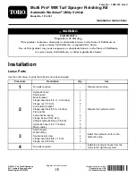
Figure 2
1.
Flange nut—1/2 inch (2)
4.
Shaft guard
2.
Hydraulic motor
5.
Flange-head bolt—1/2 x
1-1/2 inches (2)
3.
Motor bracket
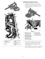
3.
Attach the anti-rotation bracket to the motor bracket
with a flange head bolt (5/16 x 3 inches), a flat washer,
2 compression springs, and a flange locknut (5/16
inch) as shown in
Note:
Torque the nut until 2 threads of the bolt
extend beyond the end of the nut.
Note:
Ensure that the bottom of the locknut is flush
with the end of the spring.
Figure 3
1.
Flange-head bolt (5/16 x 3
inches)
4.
Compression springs
2.
Flat washer
5.
Flange locknut (5/16 inch)
3.
Anti-rotation bracket
Assembling the Fittings and Hoses to
the Hydraulic Motor
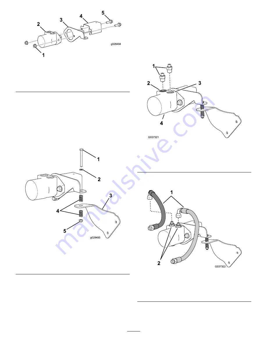
1.
Install a straight hydraulic fitting (5/8 inch) onto the
port-A of the hydraulic motor and a straight hydraulic
fitting (5/8 inch) onto the port-B of the hydraulic
motor (
Note:
Torque the fittings to 79 to 98 N∙m (58 to 72
ft-lb).
Figure 4
1.
Straight-hydraulic
fittings—7/8 inch (2)
3.
Port-B (hydraulic-motor
case)
2.
Port-A (hydraulic-motor
case)
4.
Hydraulic motor
2.
Mark the straight end of 1 hydraulic hose (1/2 x 17
inch) with a piece of tape (
).
Figure 5
1.
Hydraulic hose (1/2 x 17
inch)
3.
Straight-hydraulic fitting
(port-A)
2.
Tape marker (hydraulic
hose—port-A)
4.
Straight-hydraulic fitting
(port-B)
3.
Assemble the 90-degree fitting of the marked hydraulic
hose onto the straight fitting in port-A of the hydraulic
motor (
3

