background image

5

Installing the Speed Plates

Parts needed for this procedure:

3

Speed plate

2

Plate-mount bracket

17

Pop rivet (3/16 x 0.92 inch)

Installing the Speed Plates to the Seat
Base Sides

1.

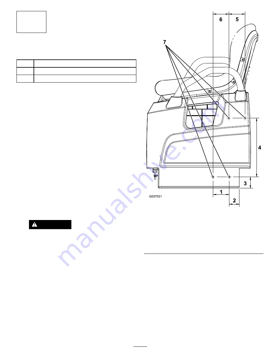
On the left side of the machine, measure 51 mm (2
inches) from bottom, left of the seat base side, and
mark this location (

Figure 11

).

2.

Measure 57 mm (2.25 inches) directly above the
location and mark this location (

Figure 11

).

3.

Measure 83 mm (3.25 inches) from the left of the
location marked in step

2

and mark this location

(

Figure 11

).

4.

Measure 80 mm (3.16 inches) from the left of the
location marked in step

3

, then measure 299 mm (11.78

inches) directly above this location, and mark this
location (

Figure 11

).

5.

Measure 83 mm (3.25 inches) from the right of the
location marked in step

4

and mark this location

(

Figure 11

).

6.

Drill a 5 mm (13/64 inch) hole at each of the 4 marked
locations (

Figure 11

).

CAUTION

Use caution when drilling the holes into the
seat base sides.

On the Workman GTX Gasoline Utility
Vehicle, the fuel tank resides behind the seat
base side on the driver’s side of the machine,
and the battery resides behind the seat base
side on the passenger’s side of the machine.

On the Workman GTX Electric Utility Vehicle,
the battery charger resides behind the seat
base side on the driver’s side of the machine.

If you drill too far into the seat base sides, you
may damage these components.

Figure 11

Left Side of the Machine Shown

1.

83 mm (3.25 inches)

5.

83 mm (3.25 inches)

2.

51 mm (2 inches)

6.

80 mm (3.16 inches)

3.

57 mm (2.25 inches)

7.

Drill at these 4 locations.

4.

299 mm (11.78 inches)

6


Summary of Contents for 133-7128

Page 1: ...rt below to verify that all parts have been shipped Procedure Description Qty Use 1 No parts required Prepare the machine Headlight 2 Headlight adapter 2 2 Cable tie 5 Install the headlights Wire harn...

Page 2: ...ded for this procedure 2 Headlight 2 Headlight adapter 5 Cable tie Procedure 1 Remove the existing left and right headlights from the headlight positions 2 Install a headlight adapter to each headligh...

Page 3: ...inches rearward from the edge of the frame cross tube and 38 mm 1 1 2 inches inward from the edge of the right sway bar mount and mark the location Figure 4 Figure 4 1 38 mm 1 1 2 inches 4 267 mm 10...

Page 4: ...screw 10 x 5 8 inch 6 Wire harness 3 Plate bracket 7 Edge clips 4 Existing bolts 8 Front of the cargo bed 2 Remove the existing edge clips from the wire harness Figure 5 3 Secure the wire harness to t...

Page 5: ...l Kit wire harness 2 Wire harness from this kit 8 Use cable ties to secure the wire harness to the machine 4 Installing the Serial Plate Parts needed for this procedure 1 Serial plate Procedure 1 Inst...

Page 6: ...5 Measure 83 mm 3 25 inches from the right of the location marked in step 4 and mark this location Figure 11 6 Drill a 5 mm 13 64 inch hole at each of the 4 marked locations Figure 11 CAUTION Use cau...

Page 7: ...ailgate 1 On the right side of the tailgate measure 95 mm 3 75 inches from the right edge of the tailgate and 70 mm 2 75 inches from the top of the tailgate and mark the location Figure 14 2 Measure 1...

Page 8: ...6 Completing the Installation No Parts Required Procedure Install the negative battery cable to the battery 8...

Reviews: