21
Steering Adjustment
If the tractor turns tighter in one direction than the other,
or if the ball joints are being replaced due to damage or
wear, the steering drag links may need to be adjusted.
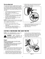
Adjust the drag links so that equal lengths are threaded
into the ball joint on the left side and the ball joint on the
right side:
1.
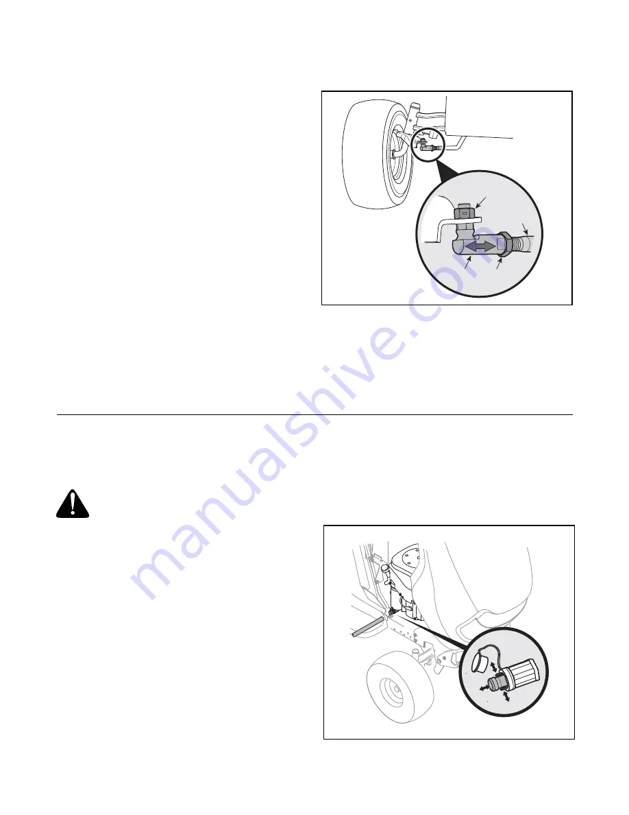
Loosen the jam nut found on the drag link at the
rear of the ball joint. See Figure 16 .
2.
Remove the hex nut on the top of ball joint.
SeeFigure 16 .
3.
Thread the ball joint toward the jam nut to shorten
the drag link. Thread the ball joint away from the
jam nut to lengthen the drag link.
4.
Replace hex nut and retighten the jam nut after
proper adjustment is achieved.
NOTE:
Threading the ball joints too far onto the drag
links will cause the front tires to "toe-in" too far. Proper
toe-in is between 1/16" and 5/16".
Front tire toe-in can be measured as follows:
1.
Place the steering wheel in position for straight
ahead travel.
2.
In front of the axle, measure the distance
horizontally from the inside of the left rim to the
inside of the right rim. Note the distance.
3.
Behind the axle, measure the distance horizontally
from the inside of the left rim to the inside of the
right rim. Note the distance.
Figure 16
4.
The measurement taken in front of the axle should
be between 1/16" and 5/16" less than the
measurement taken behind the axle.
5.
Adjust if necessary.
SECTION 8: MAINTAINING YOUR LAWN TRACTOR
NOTE:
Refer to
Maintenance Chart
on page 26 for a
reference of recommended maintenance intervals.
WARNING:
Before performing any
maintenance or repairs, disengage PTO, set
parking brake, stop engine and remove key to
prevent unintended starting.
Engine
Refer to the separate engine manual for engine
maintenance instructions.
Check
engine oil level
before each use as instructed in
the separate engine manual packed with your unit.
Read and follow instructions carefully.
Changing Engine Oil
NOTE:
Depending on the engine model found on your
tractor, it may be necessary to remove the tractor’s side
panel in order to replace the oil filter (if so equipped).
1.
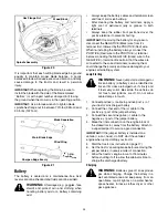
Pop open the protective cap on the end of the oil
drain valve to expose the drain port. See Figure 17 .
2.
Remove the oil fill cap/ dipstick from the oil fill tube.
3.
Push the oil drain hose (packed with this manual)
onto the oil drain port. Route the opposite end of
the hose into an appropriate oil collection container
with a capacity great enough to collect the used oil.
4.
Pinch the tabs on the oil drain valve, then pull
outward to begin draining oil. See Figure 17 .
Figure 17
Drag Link
Hex Nut
Jam
Nut
Ball
Joint
Summary of Contents for 14AQ81RP848
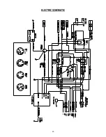
Page 30: ...30 ELECTRIC SCHEMATIC ...
Page 34: ...34 notes ...
Page 35: ...35 notes ...
Page 36: ...33 notes ...

