Brake Maintenance
Adjusting the Parking
Brake
Service Interval:
Every 500 hours
Note:
Perform this procedure whenever you remove
or replace a brake component.
1.
Park the machine on a level surface, disengage
the blade-control switch (PTO), and engage the
parking brake.
2.
Shut off the engine, remove the key, and wait
for all moving parts to stop before leaving the
operating position.
3.
Set up the machine to be pushed by hand.
Refer to
Using the Drive-Wheel Release Valves
(page 30)
.
4.
Raise the back of the machine up and support
the machine with jack stands.
WARNING
Relying solely on mechanical or
hydraulic jacks to support a raised
machine for service or maintenance
could be dangerous because the jacks
may not provide enough support or may
malfunction, allowing the machine to fall
and possibly cause serious injury.
Do not rely solely on mechanical
or hydraulic jacks for support. Use
adequate jack stands or equivalent
support.
5.
Engage and disengage the parking brake and
check each drive tire to ensure that each brake
engages and disengages.
6.
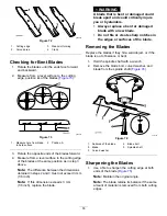
If an adjustment is necessary, disengage the
parking brake. Remove the cotter pin from the
brake linkage shaft (
).
g036752
Figure 58
1.
Cotter pin
3.
Brake linkage shaft
2.
Parking brake
7.
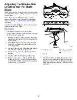
Check both spring lengths as shown in
. If an adjustment is necessary, turn the
top nut clockwise to shorten the spring and
counterclockwise to lengthen it.
g036100
Figure 59
1.
Top nut
3.
44 mm (1-3/4 inches)
2.
Spring
8.
Push the parking brake lever all the way forward
and down.
46
Summary of Contents for 2000 Series
Page 2: ......
Page 65: ...Schematics g037072 Wire Diagram Rev A 63 ...
Page 136: ...Schaltbilder g037072 Schaltbild Rev A 70 ...
Page 138: ......
Page 209: ...Schémas g037072 Schéma de câblage Rev A 71 ...
Page 279: ...Schema s g037072 Elektrisch schema Rev A 69 ...


