Traction Pedal
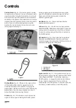
(Fig. 8)—The traction pedal: 1) makes
the machine move forward, 2) moves it backward and 3)
stops the machine. Using the heel and toe of your right
foot, depress the top of the pedal to move forward and
the bottom of the pedal to move backward or to assist in
stopping when moving forward. Also, allow the pedal to
move or move it to the neutral position to stop the
machine. Do not rest the heel of your foot on reverse
when going forward (Fig. 9).
Figure 8
1. Traction
pedal
2. Parking
brake
Figure 9
1.
Forward
2.
Reverse
Parking Brake
(Fig. 8)—Whenever the engine is shut
off, the parking brake must be engaged to prevent
accidental movement of the machine. To engage the
parking brake, pull back on the lever. After releasing the
parking brake, move the mower slightly in reverse to
release the brakes before moving forward.
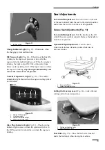
Throttle
(Fig. 10)—The throttle is used to operate the
engine at various speeds. Moving the throttle upward
increases engine speed; downward decreases engine
speed. The throttle also controls the speed of the reel
blades and, with the traction pedal, controls the
machine’s ground speed.
Hour Meter
(Fig. 10)—Shows total hours that the
machine has been operated.
Lift Lever
(Fig. 10)—The lift lever has four positions:
LOWER, RAISE, NEUTRAL and FLOAT. To lower the
cutting units to the ground, move the lift lever forward.
To raise the cutting units, pull the lift lever rearward to
the RAISE position.
PTO Switch
(Fig. 10)—The switch has two positions:
ENGAGE and DISENGAGE. Push the switch lever
forward to engage the cutting units. Pull the switch level
rearward to disengage the cutting units.
Figure 10
1. Throttle
control
2. Choke
control
3. PTO
switch
4. Cutting unit lift lever
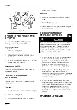
Ignition Switch (Fig. 11)—The ignition switch, used to
start and stop the engine, has three positions: OFF, RUN
(Glow Plug) and START. Turn the key clockwise—
START position—to engage the starter motor. Release
the key when the engine starts. The key will move
automatically to the ON position. To shut the engine off,
turn the key counterclockwise to the OFF position.
14
Controls
2
1
2
1
4
2
3
1
Summary of Contents for 2003
Page 16: ...Figure 15 1 Fuel valve Controls 16 1 ...
Page 24: ...Figure 25 Figure 26 Figure 27 Figure 28 Figure 29 Figure 30 Figure 31 24 Maintenance ...
Page 34: ......
Page 35: ......
Page 36: ......


