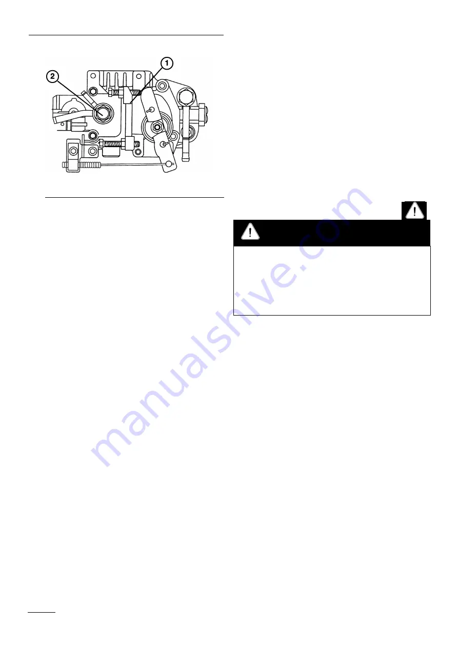
Figure 16
1. Fuel injection pump
2. Air bleed screw
OPERATING THE POWER TAKE
OFF (PTO)
The power take off (PTO) switch engages and
disengages power to the electric clutch.
Engaging the PTO
1.
Release the parking brake.
2.
Release pressure on the traction pedal to stop
movement.
3.
To engage, lift the cover and move the PTO switch
forward to the “ON” position.
Disengaging the PTO
Closing the cover moves the PTO switch to the “OFF”
(disengaged) position.
DRIVING FORWARD OR
BACKWARD
Place the throttle control in the 3/4 position for best
performance.
Forward
1.
To go forward, place your foot on the traction pedal.
2.
Release the parking brake.
3.
Slowly press on the upper pad of the traction
control to move forward.
Backward
1.
To go backward, place your foot on the traction
pedal.
2.
Release the parking brake.
3.
Slowly press on the lower pad of the traction pedal
to move rearward.
CHECK OPERATION OF
INTERLOCK SWITCHES
1.
With the operator off the seat, the traction pedal in
neutral and the PTO switch in the disengage
position, the engine should start. If either the
traction pedal is depressed or the PTO switch is
engaged, the engine should stop. Correct the
problem if the system is not operating properly.
2.
With the operator in the seat, the parking brake
engaged and the engine running, depress the
traction pedal either forward or reverse. The engine
should stop. Correct the problem if the system is not
operating properly.
3.
With the operator in the seat, the parking brake
engaged and engine running, lower the cutting units
to the ground. Engage the PTO switch, the electric
clutch on the engine should engage. Raise the
cutting units, the PTO switch should disengage.
Correct the problem if the system is not operating
properly.
IMPLEMENT LIFT LEVER
Operation
18
Do not disconnect the safety switches because they are
for the operator’s protection. Check switch operation
daily to be sure the system is operating correctly. If a
switch is not operating correctly, replace it before
operating the machine. Replace the switches every two
years to be sure of maximum safety.
CAUTION
Summary of Contents for 2003
Page 16: ...Figure 15 1 Fuel valve Controls 16 1 ...
Page 24: ...Figure 25 Figure 26 Figure 27 Figure 28 Figure 29 Figure 30 Figure 31 24 Maintenance ...
Page 34: ......
Page 35: ......
Page 36: ......


