background image

27

Maintenance

the engine.

3. 

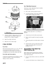
Move the cable until the speed control lever
contacts the idle speed screw.

Figure 36

1. Throttle 

cable

2. Cable 

clamp

3.  Speed control lever
4.  Idle speed screw

4. 

Tighten the cable clamp screw and check the engine
RPM setting.

ADJUSTING IDLE SPEED (Fig. 36)

1. 

Move the remote throttle control lever to the SLOW
position.

2.

Loosen the lock nut on the idle speed screw.

3. 

Adjust the idle speed screw to obtain 1100 rpm.

4. 

Tighten the lock nut.

CHECKING THE PARKING BRAKE

1

Park the machine on a level surface, disengage the
PTO switch, set the parking brake and turn the
ignition key to “OFF” to stop the engine. Remove
the key.

2

The drive wheels must lock when the brake is
applied. Adjustment is required if the wheels turn
and do not lock; refer to Adjusting the Brake.

3

Release the brake; wheels should turn freely.

4

If both conditions are met, no adjustment is
required.

IMPORTANT: With the parking brake released, the
drive wheels must turn freely. If brake action and
free wheel rotation cannot be achieved, contact your
service dealer immediately.

ADJUSTING THE PARKING
BRAKE (Fig. 37)

If drive wheels do not turn when the brake lever is in the
OFF position, or the brake does not hold when the lever
is in the ON position, an adjustment is required.

1

Move the brake lever to the ON position.

2

Measure the distance between the disc brake
actuating arm and the stop pin on the axle bracket
assembly. Distance should be less than 6 mm.

3

If the distance is greater than 6 mm, tighten the
locknut to decrease distance.

4

With the brake lever OFF, check the clearance
between the brake pads and the disc with a feeler
gauge. Correct clearance is approximately 2.5 mm
(.010 in.).

5

The actuating arm should be no more than 10 mm
away from STOP with the brake lever in the OFF
position.

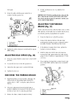
Figure 37

1.

Brake actuating arm

2.

Stop pin

3.

Locknut

4.

Disc pad

5.

Disc

Summary of Contents for 2003

Page 1: ...DEL 02003 90001 AND UP GROUNDS PRO 2000 D The TORO Company 1999 To understand this product and for safety and optimum performance read this manual before starting operation Pay special attention to SAFETY INSTRUCTIONS highlighted by this symbol ...

Page 2: ... instructions read pages 3 5 IMPORTANT highlights special mechanical information and NOTE emphasizes general product information worthy of special attention Whenever you have questions or need service contact your local authorized Toro Distributor In addition to having a complete line of accessories and professional turf care service technicians the distributor has a complete line of genuine TORO ...

Page 3: ...ere the equipment is to be used and remove all objects which may be thrown by the machine 3 WARNING Petrol is highly flammable Store fuel in containers specifically designed for this purpose Refuel outdoors only and do not smoke while refueling Add fuel before starting the engine Never remove the cap of the fuel tank or add petrol while the engine is running or when the engine is hot If petrol is ...

Page 4: ...ore removing the grass catcher before making height adjustments unless the adjustment can be made from the operator s position before clearing blockages before checking cleaning or working on the lawn mower after striking a foreign object Inspect the lawn mower for damage and make repairs before restarting and operating the equipment 15 Reduce the throttle setting during engine runout and if the e...

Page 5: ...nes per Directive 91 386 EEC and amendments Vibration Levels This unit has a vibration level of 2 5 m s2 at the hands based on measurements of identical machines per ISO 5349 procedures This unit does not exceed a vibration level of 0 5 m s2 at the posterior based on measurements of identical machines per ISO 2631 procedures Safety Instructions 5 ...

Page 6: ...glement implement input drive line Fingers or hand entangle ment chain drive Runover back over relevant machine to appear in dashed box Machine tipping riding mower Machine rollover ROPS relevant machine to appear in dashed box Stored energy hazard kickback or upward motion Hot surfaces burns to fingers or hands Hand arm entanglement belt drive Thrown or fly ing objects whole body exposure Thrown ...

Page 7: ...rs Fast Slow Continuous variable linear Volume empty Volume full Machine travel direction forward rearward Control lever operating direction dual direction Control lever operating direction multiple direction Clockwise rotation Counter clock wise rotation Grease lubrication point Oil lubrication point Lift point Jack or support point Draining emptying Engine lubricat ing oil Engine lubricating oil...

Page 8: ...l drive Power Take Off Power Take Off rotational speed Reel cutting element Reel cutting element height adjustment Traction Above working temperature range Drilling Manual metal arc welding Manual 0356 Water pump 0626 Keep dry 0430 weight Do not dispose in the garbage CE logo Engine coolant pressure Engine coolant f ilter Engine lubricating oil pressure Engine intake combustion air Engine intake c...

Page 9: ...ted by a control lever Main Frame All steel welded construction utilizing tubular and formed sheet metal sections Seat Standard cushion seat and optional deluxe suspension seat with arm rest and weight adjustment The seat is adjustable fore and aft Arm rest kit also available Lift System Category 0 A Frame mounting system connected to the tractor via parallel linkage One double acting 60 mm bore 1...

Page 10: ...uspension Seat Kit Model No 02305 Arm Rest Kit for Model 30769 Model No 30707 Debris Blower Model No 02202 Large Pulley Kit Part No 98 5413 Roller Scraper Kit Part No 60 9560 Comb Kit Part No 67 9400 Rear Weight Part No 24 5790 Rear Weight 2 Part No 24 5780 Gauge Bar Kit Part No 13 8199 Backlap Kit Part No 84 5510 Tire Chains Part No 82531 3 per kit Specifications 10 ...

Page 11: ...ours of operation thereafter under normal conditions change the oil every 50 hours and filter every 100 hours However change it more often when operating the engine in extremely dusty or dirty conditions 5 Install the filler cap and the dipstick CHECK THE COOLING SYSTEM Fig 2 Clean debris from the hood screens engine and radiator daily more often if conditions are extremely dusty and dirty refer t...

Page 12: ...gine oil or as a substitute SAE 10W 40 engine oil The reservoir is filled at the factory with 4 7 l of 10W 30 engine oil Check the oil level before first starting the engine and daily thereafter 1 Position the machine on a level surface and stop the engine 2 Remove the access panel to expose the hydraulic system dipstick filler cap Figure 5 1 Access panel 3 Remove the dipstick cap from the filler ...

Page 13: ...ne minute recheck the oil level and add more if needed CHECK TIRE PRESSURE Correct air pressure in front and rear tires is 84 124 kPa LUBRICATE BEARINGS AND BUSHINGS The traction unit and cutting unit s grease fittings must be lubricated with No 2 General Purpose Lithium Base Grease CHECK REEL TO BEDKNIFE CONTACT Each day before operating check reel to bedknife contact There must be light contact ...

Page 14: ...eases engine speed downward decreases engine speed The throttle also controls the speed of the reel blades and with the traction pedal controls the machine s ground speed Hour Meter Fig 10 Shows total hours that the machine has been operated Lift Lever Fig 10 The lift lever has four positions LOWER RAISE NEUTRAL and FLOAT To lower the cutting units to the ground move the lift lever forward To rais...

Page 15: ... Light Fig 12 The glow plug indicator light comes on when the ignition switch is in the RUN position but should be out when the engine is running Seat Adjustments Fore and Aft Adjustment Move the lever on the side of the seat outward slide the seat to the desired position and release the lever to lock the seat into position Deluxe Seat Adjustments Fig 13 Fore and Aft Adjustment Pull the handle on ...

Page 16: ...Figure 15 1 Fuel valve Controls 16 1 ...

Page 17: ...t to check steering response Then shut the engine off and check for oil leaks loose parts and any other noticeable malfunctions 9 To stop the engine move the throttle control downward to the SLOW position move the PTO switch to OFF and turn the ignition key to OFF Remove the key from the switch to prevent accidental starting 10 Set the parking brake 11 Close the fuel shut off valve before storing ...

Page 18: ...e seat the traction pedal in neutral and the PTO switch in the disengage position the engine should start If either the traction pedal is depressed or the PTO switch is engaged the engine should stop Correct the problem if the system is not operating properly 2 With the operator in the seat the parking brake engaged and the engine running depress the traction pedal either forward or reverse The en...

Page 19: ...e area was last mowed Always mow in an alternate pattern from the previous mowing so that the grass blades will be less apt to lay down and therefore be difficult to gather between the reel blades and bedknife OPERATING CHARACTERISTICS Practice operating the Grounds Pro 2000 D and become thoroughly familiar with it Because of its hydrostatic transmission its characteristics differ from many turf m...

Page 20: ... The single knob bedknife adjustment system simplifies the procedure for delivering optimum mowing performance The precise adjustment possible gives the control to provide a continual self sharpening action thus maintaining sharp cutting edges good quality of cut and greatly reduced need for routine backlapping Also the rear roller positioning system permits optimum bedknife attitude and location ...

Page 21: ...appear on the front cutting edge surface over the full length of the bedknife Occasionally running a file across the front edge to remove this burr will improve cutting After extended running a ridge will eventually develop at both ends of the bedknife These must be rounded off or filed flush with the cutting edge of bedknife to assure smooth operation Operation 21 ...

Page 22: ...e oil and filter Check the cutting unit s belt tension Check battery fluid connections Lubricate grease fittings Service the air cleaner Every 400 hours Every 800 hours Every 200 hours Every 100 hours Every 50 hours Every 25 hours Recommendations Items are recommended every 1000 hours or 2 years whichever occurs first Daily Maintenance Checklist Safety Interlock Operation Brake Operation Engine Oi...

Page 23: ...st be lubricated daily when operating conditions are extremely dusty and dirty Dusty and dirty operating conditions could cause dirt to get into the bearings and bushings resulting in accelerated wear Lubricate grease fittings immediately after every washing regardless of the interval listed The traction unit bearings and bushings and the cutting unit lubrication points that must be lubricated are...

Page 24: ...Figure 25 Figure 26 Figure 27 Figure 28 Figure 29 Figure 30 Figure 31 24 Maintenance ...

Page 25: ...ter 3 Screw the filter on by hand until the gasket contacts the filter adapter then tighten 1 2 to 3 4 turn further DO NOT OVER TIGHTEN 4 Add oil to the crankcase refer to CHECK THE ENGINE OIL 5 Start the engine and check for leaks around the filter 6 Dispose of the oil properly SERVICING THE AIR CLEANER Fig 34 Clean the air filter cartridge after every 25 operating hours Service it more often eve...

Page 26: ...r Drain water or other contaminants from the fuel filter water separator Fig 35 daily 1 Place a clean container under the fuel filter 2 Loosen the drain plug on the bottom of the filter canister Tighten the plug after draining Figure 35 1 Fuel filter Replace the filter canister after every 400 hours of operation 1 Clean the area where the filter canister mounts 2 Remove the filter canister and cle...

Page 27: ...eely 4 If both conditions are met no adjustment is required IMPORTANT With the parking brake released the drive wheels must turn freely If brake action and free wheel rotation cannot be achieved contact your service dealer immediately ADJUSTING THE PARKING BRAKE Fig 37 If drive wheels do not turn when the brake lever is in the OFF position or the brake does not hold when the lever is in the ON pos...

Page 28: ...al is released If it does creep an adjustment is required 1 Park the machine on a level surface lower the cutting unit and shut off the engine Disengage the PTO switch and engage the parking brake 2 Jack up the front of the machine until the tires are off the shop floor Support the machine with jack stands to prevent it from falling accidentally 3 Loosen the lock nut on the adjustment cam 4 Start ...

Page 29: ...00 hours of operation or yearly whichever comes first The reservoir has a capacity of 4 7 l 1 Park the machine on a level surface lower the cutting units engage the parking brake and shut off the engine 2 Clean the area around the hydraulic oil filter and remove the filter from the filter housing 3 Disconnect the tube and hose assembly from the reservoir and allow the oil to flow into a drain pan ...

Page 30: ... system Then shut off the engine 4 Check the level of oil refer to Check the Hydraulic System Fluid CHANGING FRONT AXLE OIL Fig 43 After every 400 hours of operation change the oil in the front axle 1 Drive the machine for five minutes before changing oil to warm the axle oil Warm oil flows more freely and carries more contaminants than cold oil 2 Clean the area around the drain plug and place a d...

Page 31: ...Skin over grease Toro Part No 505 47 to the inside of all harness connectors whenever the harness is replaced Whenever working with the electrical system always disconnect the battery cables negative cable first to prevent possible wiring damage from electrical shorts Before welding on the machine disconnect ground cable from the battery to prevent damage to the electrical system FUSES Fig 45 Ther...

Page 32: ...cerning the mower supply the model and serial numbers to assure that correct information and replacement parts are obtained Note Do not order by reference number if a parts catalog is being used use the part number To order replacement parts from an Authorized TORO Service Dealer supply the following information 1 Model and serial numbers of the mower 2 Part number description and quantity of part...

Page 33: ...old along line Align this edge with a vertical surface Tree building fence post pole etc Example Compare slope with folded edge T h i s i s a 2 0 S l o p e T h i s i s a 1 5 S l o p e 15 and 20 Slope Chart ...

Page 34: ......

Page 35: ......

Page 36: ......

Reviews: