29
Maintenance
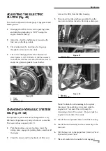
ADJUSTING THE ELECTRIC
CLUTCH (Fig. 40)
The clutch is adjusted to ensure proper engagement and
braking action.
1.
Disengage the PTO switch, set the parking brake,
and turn the ignition key to “OFF” to stop the
engine. Remove the key.
2.
Adjust the clutch by tightening or loosening the
lock nuts on the flange studs.
3.
Check adjustment by inserting a feeler gauge
through the slots next to the studs.
4.
The correct disengaged clearance between the
clutch plates is 0.23-0.30 mm. It will be necessary
to check this clearance at each of the three slots to
ensure the plates are parallel to each other.
Figure 40
1.
Clutch
2. Locknut
3. Adjustment
slot
CHANGING HYDRAULIC SYSTEM
OIL (Fig. 41–42)
The hydraulic system oil must be changed after every
400 hours of operation or yearly, whichever comes first.
The reservoir has a capacity of 4.7 l.
1.
Park the machine on a level surface, lower the
cutting units, engage the parking brake, and shut off
the engine.
2.
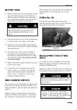
Clean the area around the hydraulic oil filter and
remove the filter from the filter housing.
3.
Disconnect the tube and hose assembly from the
reservoir and allow the oil to flow into a drain pan.
Figure 41
1. Hydraulic
filter
Figure 42
1. Reservoir
2. Hose
assembly
Note: To drain the oil remaining in the system,
disconnect the spark plug wires and crank the
engine for 15 seconds. This will pump the
remaining oil out of the system. Do not crank the
engine for more than 15 seconds.
4.
Install the new hydraulic filter to the filter housing.
5.
Install the tube assembly and hose assembly to the
reservoir.
6.
Fill the reservoir to the proper level; refer to Check
Hydraulic System Fluid.
7.
Place all controls in the neutral or disengaged
1
2
3
1
1
2
Summary of Contents for 2003
Page 16: ...Figure 15 1 Fuel valve Controls 16 1 ...
Page 24: ...Figure 25 Figure 26 Figure 27 Figure 28 Figure 29 Figure 30 Figure 31 24 Maintenance ...
Page 34: ......
Page 35: ......
Page 36: ......

