background image

Owner Responsibilities:

As the Product owner, you are responsible for required
maintenance and adjustments stated in your Owner's
Manual. Failure to perform required maintenance and
adjustments can be grounds for disallowing a warranty
claim.

Instructions for Obtaining Warranty Service:

You are responsible for notifying the Toro SiteWork
Systems Distributor or Authorized Toro SiteWork

T

Systems Dealer from whom you purchased the Product as
soon as you believe a warrantable condition exists.

If you need help locating a Toro SiteWork

T

Systems

Distributor or Authorized Dealer, or if you have questions
regarding your warranty rights or responsibilities, you may
contact us at:

Toro LCG Products Service Department

8111 Lyndale Avenue South

Minneapolis, MN, 55420-1196

Telephone: (612) 888-8801

Facsimile: (612) 887-8258

Maintenance Parts:

Parts scheduled for replacement as required maintenance

(Maintenance Parts"), are warranted for the period of time

up to the scheduled replacement time for that part.

Items/Conditions Not Covered:

Not all product failures or malfunctions that occur during

the warranty period are defects in materials or

workmanship. The items / conditions listed below are not

covered by this warranty:

D

Product failures which result from the use of non-Toro

replacement parts, or from installation and use of

add-on, modified, or unapproved accessories are not

covered.

D

Product failures which result from failure to perform

required maintenance and/or adjustments are not

covered.

D

Product failures which result from operating the Product

in an abusive, negligent or reckless manner are not

covered.

The Toro Company warrants your Toro SiteWork

T

Systems Product (Product") to be free from defects in

materials or workmanship for the period of time listed below. Where a warrantable condition exists, Toro will
repair the Product at no cost to you including diagnosis, labor, parts, and transportation. This warranty begins on
the date the Product is delivered to the original retail purchaser.

Warranty Duration: One year or 500 operational hours, whichever occurs first.

D

This warranty does not apply to parts subject to

consumption through use unless found to be defective.

Examples of parts which are consumed, or used up,

during normal Product operation include, but are not

limited to, digging teeth, tines, spark plugs, tires, filters,

chains, etc.

D

This warranty does not apply to failures caused by

outside influence. Items considered to be outside

influence include, but are not limited to, weather, storage

practices, contamination, use of unapproved coolants,

lubricants, additives, or chemicals, etc.

D

This warranty does not apply to normal wear and tear"

items. Normal Wear and Tear" includes, but is not

limited to, worn painted surfaces, scratched decals or

windows, etc.

Other Legal Disclaimers:

The above remedy of product defects through repair by an

authorized distributor or dealer is the purchaser's sole

remedy for any defect. This warranty gives you specific

legal rights, and you may also have other rights which vary

from state to state.

Except for the Emissions warranty referenced below, if

applicable, there is no other express warranty. All

implied warranties of merchantability and fitness for

use are limited to the duration of the express warranty.

Some states do not allow limitations on how long an implied

warranty lasts, so the above limitation may not apply to you.

The Toro Company is not liable for indirect, incidental

or consequential damages in connection with the use of

the Product, including any cost or expense of providing

substitute Product or service during periods of

malfunction or non-use.

Some states do not allow the exclusion of incidental or

consequential damages, so the above exclusion may not

apply to you.

Note to California residents:

The Emissions Control

System on your Product may be covered by a separate

warranty meeting requirements established by the U.S.

Environmental Protection Agency (EPA), or the California

Air Resources Board (CARB). The hour limitations set forth

above do not apply to the Emissions Control System

Warranty. Refer to the California Emission Control Warranty

Statement printed in your Owner's Manual or contained in

the engine manufacturer's documentation for details.

The Toro SiteWork

T

Systems Product Line

One Year Limited Warranty

Summary of Contents for 22302

Page 1: ...nual carefully It contains information about your safety and the safety of others Also become familiar with the controls and their proper use before you operate the product FORM NO 3321 119 DINGO 220...

Page 2: ...using the product properly and safely You are also responsible for training persons who you allow to use the product about safe operation The warning system in this manual identifies potential hazard...

Page 3: ...1 Tire pressure 11 Operation 12 Think Safety First 12 Controls 12 Starting and Stopping Engine 14 Page Driving Forward or Backward 15 Stopping the Machine 15 Moving A Non Functioning Machine 16 Using...

Page 4: ...al Operation 1 Read understand and follow all instructions in the operator s manual in the video and on the machine before starting Also read attachments manual where supplied 2 Allow only responsible...

Page 5: ...s uneven terrain could overturn the machine Tall grass can hide obstacles Use slow speed Before starting put pump selector valve in slow turtle position so that you will not have to stop or shift whil...

Page 6: ...n before each use 6 Keep the machine free of grass leaves or other debris build up Clean up oil or fuel spillage Allow the machine to cool before storing 7 Use extra care when handling gasoline and ot...

Page 7: ...Safety 5 Slope Chart Read all safety instructions on pages 2 4...

Page 8: ...4682 On Control Panel Part No 98 4676 Near Oil Fill Part No 85 4730 On Front Control Panel Part No 98 4677 On Front Control Panel Part No 98 8220 On Control Panel Part No 52 1320 On Control Panel Par...

Page 9: ...e levers Key Training Video Operator s Manual Registration card 2 1 1 1 View before operating machine Read before operating machine Fill out and return to Toro Install Valve Levers 1 Thread a lever in...

Page 10: ...each fully raised 26 0 inches 66 cm with std bucket Height to hinge pin 66 0 inches 168 cm std bucket in highest position Specifications and design subject to change without notice Approved Attachment...

Page 11: ...Fuel Tank 1 Park the machine on a level surface lower the loader arms and turn the ignition key to OFF to stop the engine Remove the key 2 Clean around the fuel tank cap and remove the cap Use a funn...

Page 12: ...r certain conditions fuel is extremely flammable and highly explosive WHAT CAN HAPPEN A fire or explosion from fuel can burn you others and cause property damage HOW TO AVOID THE HAZARD Use a funnel a...

Page 13: ...he machine on a level surface lower the loader arms and turn the ignition key to OFF to stop the engine Remove the key 2 Clean around the oil dipstick Fig 3 4 so dirt cannot fall into the filler hole...

Page 14: ...burns HOW TO AVOID THE HAZARD Do not remove the radiator cap when the engine is hot Always allow the engine to cool at least 15 minutes or until the radiator cap is cool enough to touch without burni...

Page 15: ...the hydraulic fluid level before engine is first started and after every 25 operating hours Fluid Type Mobil Fluid 424 ISO 46 or equivalent anti wear hydraulic fluid IMPORTANT Use only group 1 hydrau...

Page 16: ...s specified Check the tires when they are cold to get the most accurate pressure reading Pressure 15 22 psi Note It may be beneficial to use lower tire pressure when operating in sandy soil conditions...

Page 17: ...hold for 5 7 seconds then to START position to engage starter motor Release key when engine starts The key will move automatically to the ON position To shut engine off rotate key counterclockwise to...

Page 18: ...n slowly pull auxiliary hydraulics lever rearward To operate attachment in reverse direction slowly push auxiliary hydraulics lever forward Pump selector lever When faster ground speed and lifting spe...

Page 19: ...quire less glow time 6 Turn ignition key to START to energize starter When engines starts release key IMPORTANT Do not engage starter for more than 10 seconds at a time If engine fails to start allow...

Page 20: ...ove the traction control levers to neutral Backward To go backward slowly pull the traction control levers rearward Fig 8 To go straight apply equal force to both traction control levers Fig 8 To turn...

Page 21: ...when in the raised position WHAT CAN HAPPEN Anyone under loader arms may be injured or crushed HOW TO AVOID THE HAZARD Always install cylinder locks when doing maintenance that requires raised loader...

Page 22: ...to engage Note Proceed to next step if auxiliary hydraulics are required with attachment IMPORTANT Make sure all foreign matter is cleaned from hydraulic connections before making connections 7 Move...

Page 23: ...always use the following procedure 1 Lower the loader arms 2 Turn the ignition key to OFF to stop the engine 3 Secure the machine to the trailer with chains or straps using the rear platform support o...

Page 24: ...on Drive Chain lubrication X Wheel Nuts tighten Initial Chassis grease X Air Cleaner Pre Cleaner empty X X Paper Air Cleaner service X Paper Air Cleaner replace X Engine RPM high low idle check X Fuel...

Page 25: ...Servicing Dust Cup And Baffle Inspect the dust cup and rubber baffle once a week or every 50 hours operation However daily or more frequent inspection is required when operating conditions are extreme...

Page 26: ...r from inside to the outside of dry filter element Do not exceed 100 psi to prevent damage to the element E Keep air hose nozzle at least one inch from pleated paper and move nozzle up and down while...

Page 27: ...han the opposite side to assure the oil drains completely Then lower the loader arms and turn the ignition key to OFF to stop the engine Remove the key POTENTIAL HAZARD Components will be hot if the t...

Page 28: ...25 2 Place a drip pan beneath the oil drip tray to receive oil from the oil filter and oil passages in the engine 3 Turn the filter counterclockwise to remove it Note Dispose of oil filter properly R...

Page 29: ...ol then remove the radiator cap Fig 12 1 Figure 12 1 Radiator cap Note If you wish you can attach a 3 8 ID hose to each of the two drain valves 3 Open both coolant drain valves at the bottom of the ra...

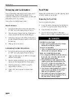
Page 30: ...Apply oil to newly exposed un lubed chain spans Fuel Filter Replace the fuel filter after every 400 operating hours or yearly whichever occurs first Replacing the Fuel Filter Never re install a dirty...

Page 31: ...loader arms and turn the ignition key to OFF to stop the engine Remove the key 3 Open fuel shut off on fuel filter and open fuel cap vent POTENTIAL HAZARD Under certain conditions fuel is extremely f...

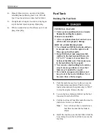
Page 32: ...o the fuel tank until the level is 1 4 to 1 2 6 mm to 13 mm below the bottom of the filler neck This empty space in the tank allows fuel to expand Never smoke when handling fuel and stay away from an...

Page 33: ...p the engine and check for leaks 7 Check fluid level in hydraulic tank and add to raise level to mark on dipstick DO NOT OVER FILL Changing the Hydraulic Fluid Change the hydraulic fluid After every 4...

Page 34: ...familiar with this form of injury or gangrene may result HOW TO AVOID THE HAZARD Keep body and hands away from pin hole leaks or nozzles that eject high pressure hydraulic fluid Use cardboard or paper...

Page 35: ...elt should have a maximum deflection of 25 35 inch 7 9mm with a 22 pound 10Kg load applied 1 Position machine on a level surface lower the loader arms stop the engine and remove key from ignition swit...

Page 36: ...mix thoroughly with the electrolyte solution 1 Clean the top of the battery with a paper towel 2 Lift off the filler caps Fig 16 3 Slowly pour distilled water into each battery cell until the level is...

Page 37: ...8 5 Change the crankcase oil refer to Engine Oil page 25 6 Change the hydraulic fluid refer to Hydraulic System page 31 7 Check the tire pressure refer to Tire Pressure page 14 8 Charge the battery re...

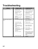
Page 38: ...ed Service Dealer The engine cranks but will not start 1 Incorrect starting procedure 1 Refer to Starting and Stopping the Engine page 17 2 The fuel tank is empty 2 Fill with fresh fuel 3 The fuel shu...

Page 39: ...ce the fuel filter Add fresh fuel of proper grade for ambient temperature conditions The engine starts but does not keep running 1 The fuel tank vent is restricted 1 Contact your Authorized Service De...

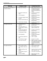
Page 40: ...ale fuel or incorrect fuel is in the fuel system 2 Drain and flush the fuel system add fresh fuel 3 The idle speed adjusting screw is incorrectly set 3 Contact your Authorized Service Dealer 4 The fue...

Page 41: ...is overheated 4 See ENGINE OVERHEATS 5 Low compression 5 Contact your Authorized Service Dealer 6 The fuel tank vent is restricted 6 Contact your Authorized Service Dealer 7 The engine load is excess...

Page 42: ...The injection pump timing is incorrect 4 Contact your Authorized Service Dealer 5 Low compression 5 Contact your Authorized Service Dealer Machine does not drive 1 Traction pump drive coupler is loose...

Page 43: ......

Page 44: ...erational hours whichever occurs first D This warranty does not apply to parts subject to consumption through use unless found to be defective Examples of parts which are consumed or used up during no...

Reviews: