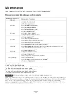
8
98-8219
1.
Fast
2.
Throttle
3.
Slow
98-8235
1.
Fast
2.
Traction drive
3.
Slow
1
1
#93-7814
1.
Entanglement hazard—stay away from moving parts
93-9084
1.
Lift point
2.
Tie-down point
98-4677
Assembly
Note: Determine the left and right side of the machine from the normal operating position.
Loose Parts
Note: Use the chart below to verify that all parts have been shipped.
DESCRIPTION
QTY.
USE
Traction Unit
Valve Lever
1
1
Install valve lever
Key
2
Start engine
Hydraulic oil filter
1
Break-in oil change
Installing the Valve Lever
1. Thread the lever into the speed selector valve (Fig. 2).
Note: The lever should be installed with the bend toward
the operator.
2. Tighten the jam nut on the lever to lock it in position.
Summary of Contents for 22303
Page 6: ...6 Slope Chart...
Page 35: ...35...


