between attempts. Failure to follow these
instructions can burn out the starter motor.
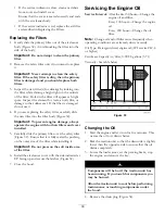
6. Move the throttle lever to desired setting.
Important:
If the engine is run at high speeds
when the hydraulic system is cold (i.e., when
the ambient air temperature is near freezing or
lower), hydraulic system damage could occur.
When starting the engine in cold conditions,
allow the engine to run in the middle throttle
position for 2 to 5 minutes before moving the
throttle to fast (rabbit).
Note:
If outdoor temperature is below freezing,
store the traction unit in a garage to keep it warmer
and aid in starting.
Stopping the Engine
1. Move the throttle lever to the slow (turtle) position.
2. Lower the loader arms to the ground.
3. Turn the ignition key off.
Note:
If the engine has been working hard or
is hot, let it idle for a minute before turning the
ignition key off. This helps cool the engine before
it is stopped. In an emergency, the engine may be
stopped immediately.
Stopping the Traction Unit
To stop the traction unit, release the traction control,
move the throttle lever to slow (turtle), lower loader
arms to the ground, and stop the engine. Set the
parking brake and remove the key.
A child or untrained bystander could attempt to
operate the traction unit and be injured.
Remove the key from the switch when leaving
the traction unit, even if just for a few seconds.
Moving a Non-functioning
Traction Unit
Important:
Do not tow or pull the traction
unit without first opening the tow valves, or the
hydraulic system will be damaged.
1. Stop the engine.
2. Open the rear access cover.
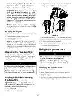
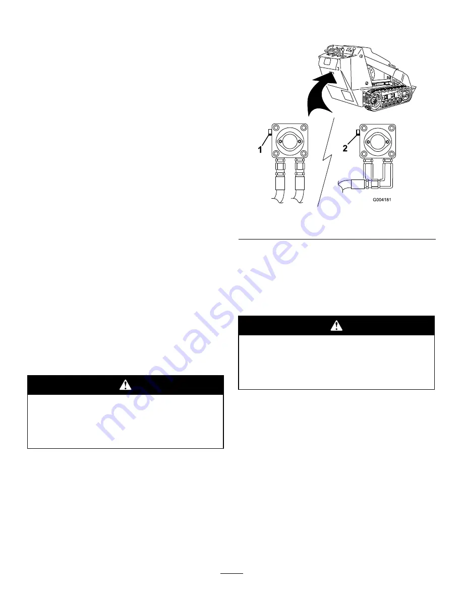
3. Using a wrench, turn the tow valves on the hydraulic
pumps twice counter-clockwise (Figure 22).
Figure 22
1.
Left tow valve (right track)
2.
Right tow valve (left track)
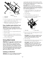
4. Tow the traction unit as required.
5. When the traction unit has been repaired, close the
tow valves before operating it.
Using the Cylinder Lock
The loader arms may lower when in the raised
position crushing anyone under them.
Install the cylinder lock before performing
maintenance that requires raised loader arms.
Installing the Cylinder Lock
1. Remove the attachment.
2. Raise the loader arms to the fully raised position.
3. Stop the engine.
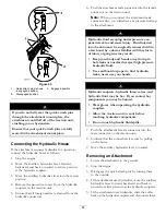
4. Remove the lynch pin securing the cylinder lock to
the loader arm (Figure 23).
22
Summary of Contents for 22319
Page 7: ...Slope Indicator 7...
Page 49: ...Schematics G007388 Electrical Schematic Rev B 49...
Page 50: ...Hydraulic Schematic Rev A 50...
Page 51: ...Notes 51...

