background image

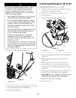
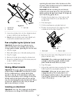
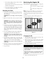
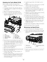
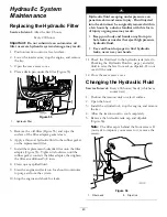
Figure 34

1.

Oil drain plug

5. When the oil has drained completely, replace the

plug.

Note:

Dispose of the used oil at a certified recycling

center.

6. Remove the oil fill cap and slowly pour approximately

80% of the specified amount of oil in through the
valve cover.

7. Check the oil level; refer to Checking the Engine Oil

Level in , page .

8. Slowly add additional oil to bring the level to the

upper hole on the dipstick.

9. Replace the fill cap.

Changing the Oil Filter

1. Drain the oil from the engine; refer to Changing

the Oil.

2. Place a shallow pan or rag under the filter to catch oil.

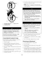
3. Remove the old filter (Figure 35) and wipe the

surface of the filter adapter gasket.

Figure 35

1.

Oil filter

4. Pour new oil of the proper type through the center

hole of the filter. Stop pouring when the oil reaches
the bottom of the threads.

5. Allow a minute or two for the oil to be absorbed by

filter material, then pour off the excess oil.

6. Apply a thin coat of new oil to the rubber gasket

on the replacement filter.

7. Install the replacement oil filter to the filter adapter.

Turn the oil filter clockwise until the rubber gasket
contacts the filter adapter, then tighten the filter an
additional 1/2 turn.

8. Fill the crankcase with the proper type of new oil;

refer to Changing the Oil.

31

Summary of Contents for 22319

Page 1: ...Utility Loader Model No 22323 Serial No 290000001 and Up Model No 22324 Serial No 290000001 and Up G004222 To register your product or download an Operator s Manual or Parts Catalog at no charge go to...

Page 2: ...ngine manufacturer Introduction Read this information carefully to learn how to operate and maintain your product properly and to avoid injury and product damage You are responsible for operating the...

Page 3: ...e Screens 28 Lubrication 29 Greasing the Traction Unit 29 Engine Maintenance 29 Servicing the Air Cleaner 29 Servicing the Engine Oil 30 Fuel System Maintenance 32 Checking the Fuel Lines and Connecti...

Page 4: ...o be used and remove all objects such as rocks toys and wire which can be thrown by the machine Use extra care when handling fuels They are flammable and vapors are explosive Use only an approved cont...

Page 5: ...es exceeding the angles recommended in the Stability Data section in page and those in the attachment Operator s Manual See also the page Operate up and down slopes with the heavy end of the traction...

Page 6: ...action unit free of grass leaves or other debris build up Clean up oil or fuel spillage Allow the traction unit to cool before storing Use extra care when handling fuels They are flammable and vapors...

Page 7: ...Slope Indicator 7...

Page 8: ...belt stay away from moving parts 100 4650 1 Crushing hazard of hand keep bystanders a safe distance from the machine 2 Crushing hazard of foot keep bystanders a safe distance from the machine 100 882...

Page 9: ...load rating of 500 lb 228 Kg no riders 115 4857 1 Lower the loader arms 4 Curl the bucket 2 Dump the bucket 5 Float the bucket on the ground 3 Raise the loader arms 115 4858 1 Crushing hazard of hands...

Page 10: ...immediately with water and get medical help fast 5 Read the Operator s Manual 10 Contains lead do not discard 115 4860 1 Warning read the Operator s Manual 2 Warning set the parking brake stop the en...

Page 11: ...il pressure 12 Continuous variable setting engine speed 17 Tipping hazard move the traction unit with the heavy end up hill do not travel with the loader arms raised 3 Engine run 8 Battery 13 Slow 4 E...

Page 12: ...and glow plug switch 11 Loader valve lock 6 Throttle lever Key Switch The key switch used to start and stop the engine has three positions off run and start To start the engine rotate the key to the s...

Page 13: ...8132 Figure 9 To stop release the traction control Figure 5 Note The farther you move the traction control in any direction the faster the machine will move in that direction Loader Arm Attachment Til...

Page 14: ...ate the auxiliary hydraulics lever rearward and pull it down to the reference bar Figure 12 number 1 To operate a hydraulic attachment in reverse direction rotate the hydraulics lever rearward then mo...

Page 15: ...ubject to change without notice Model 22323 Specifications Width 34 inches 86 cm Length 71 inches 180 cm Height 46 inches 117 cm Weight 1904 lb 864 Kg Operating capacity 553 lb 251 Kg Tipping capacity...

Page 16: ...has a Front Uphill rating of B a Rear Uphill rating of D and a Side Uphill rating of C then you could drive forward up a 19 slope rearward up a 12 slope or sideways on a 14 slope as listed in the fol...

Page 17: ...d prolonged breathing of vapors Keep face away from nozzle and fuel tank or conditioner opening Keep fuel away from eyes and skin Biodiesel Ready This machine can also use a biodiesel blended fuel of...

Page 18: ...times until fueling is complete 1 Remove the fuel tank cap Figure 15 Figure 15 1 Fuel tank cap 2 Fill the tank to about one inch below the top of the tank not the filler neck with diesel fuel 3 Instal...

Page 19: ...fully retract the tilt cylinder 3 Stop the engine remove the key and allow the engine to cool 4 Open the hood 5 Clean the area around the filler neck of the hydraulic tank Figure 17 Figure 17 1 Hydra...

Page 20: ...pen the cap slowly to allow steam to escape Rotating shaft and fan can cause personal injury Do not operate the machine without the covers in place Keep fingers hands and clothing clear of rotating fa...

Page 21: ...d stay away from an open flame or where fuel fumes may be ignited by a spark Store fuel in a clean safety approved container and keep the cap in place 1 Ensure that the fuel tank is at least half full...

Page 22: ...on control move the throttle lever to slow turtle lower loader arms to the ground and stop the engine Set the parking brake and remove the key A child or untrained bystander could attempt to operate t...

Page 23: ...hould ignore any references to them Installing an Attachment Important Use only Toro approved attachments Attachments can change the stability and the operating characteristics of the traction unit Th...

Page 24: ...under pressure can penetrate skin and cause injury Fluid injected into the skin must be surgically removed within a few hours by a doctor familiar with this form of injury or gangrene may result Keep...

Page 25: ...ort When transporting the traction unit on a trailer always use the following procedure Important Do not operate or drive the traction unit on roadways 1 Lower the loader arms 2 Stop the engine 3 Secu...

Page 26: ...ery cable connections Check and adjust the track tension Check the cooling system hoses Check the alternator fan belt tension refer to the Engine Operator s Manual for instructions Check the hydraulic...

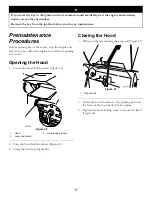
Page 27: ...engine to cool before opening any covers Opening the Hood 1 Loosen the hood locking screw Figure 26 3 G009691 Figure 26 1 Hood 3 Hood locking screw 2 Lever hood latch 2 Turn the hood latch clockwise...

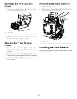
Page 28: ...ack of the traction unit making sure the tabs line up in the slots 2 Push the access cover forward lining up the hand knob screws with the threaded holes in the machine 3 Screw the hand knobs tight to...

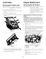
Page 29: ...over and Body Important Service the air cleaner filter only when the service indicator shows red Figure 32 Changing the air filter before it is necessary only increases the chance of dirt entering the...

Page 30: ...stalled 5 Carefully slide the primary filter over the safety filter Figure 32 Ensure that it is fully seated by pushing on the outer rim of the filter while installing it Important Do not press on the...

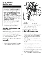
Page 31: ...ow pan or rag under the filter to catch oil 3 Remove the old filter Figure 35 and wipe the surface of the filter adapter gasket Figure 35 1 Oil filter 4 Pour new oil of the proper type through the cen...

Page 32: ...ator Service Interval Before each use or daily 1 Locate the fuel filter on the right side of the engine Figure 36 and place a clean container under it Figure 36 1 Fuel filter canister water separator...

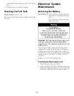
Page 33: ...ifornia to cause cancer and reproductive harm Wash hands after handling Important The following procedures apply when servicing a dry battery that has replaced the original battery The original wet ba...

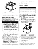
Page 34: ...overfill the battery because electrolyte sulfuric acid can cause severe corrosion and damage to the chassis 5 Wait five to ten minutes after filling the battery cells Add distilled water if necessary...

Page 35: ...ood 3 Pull the hairpin cotter from the bottom end of the hood prop rod and slide the prop rod out of the retaining brackets and the prop rod tab Figure 40 Figure 40 1 Prop rod tab 4 Retaining bracket...

Page 36: ...e track area Do not use a high pressure washer to clean the rest of the traction unit Do not use high pressure water between the drive sprocket and the traction unit or you may damage the motor seals...

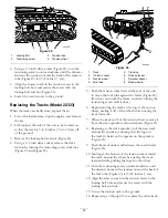
Page 37: ...8 Road wheels 5 Push the tension wheel toward the rear of the unit to move the fork tube against the frame Figure 45 If it does not touch the frame continue turning the tensioning screw until it does...

Page 38: ...area between where the washers were installed and the bearings inside the wheels then fill this area on each side of each wheel with grease 11 Install the large washers on the wheels over the grease...

Page 39: ...ng System Maintenance Servicing the Cooling System Service Interval Before each use or daily Clean the radiator Every 100 hours Check the cooling system hoses Yearly Change the engine coolant Authoriz...

Page 40: ...ding and Bleeding the Engine Coolant in page Belt Maintenance Checking the Condition of the Hydraulic Pump Belt Service Interval Yearly Check the condition of the hydraulic pump belt Figure 49 yearly...

Page 41: ...he front of the control contacts the reference bar Figure 50 Figure 50 1 Front of the control out of alignment 2 Reference bar 4 If the front of the traction control does not rest square and flush wit...

Page 42: ...ent previously described so that it tracks straight in reverse Adjusting the Tracking of the Traction Control Full Forward Position If the traction unit does not drive straight when you hold the tract...

Page 43: ...ystem 10 Stop the engine and check for leaks Hydraulic fluid escaping under pressure can penetrate skin and cause injury Fluid injected into the skin must be surgically removed within a few hours by a...

Page 44: ...fluid level and top it off if necessary refer to Checking Hydraulic Fluid in page 13 Close the hood Checking the Hydraulic Lines Service Interval Every 100 hours Check the hydraulic lines for leaks lo...

Page 45: ...Using a flashlight open the hood and inspect the area under the engine on a regular basis When the debris is 1 to 2 inches deep have an Authorized Service Dealer remove the rear of the traction unit...

Page 46: ...our Authorized Service Dealer 9 The air cleaner filters are dirty 9 Service the air filters 10 The fuel filter is clogged 10 Replace the fuel filter 11 Improper fuel grade for cold weather use 11 Drai...

Page 47: ...connections and fittings between the fuel tank and engine 6 The fuel pump is damaged 6 Contact your Authorized Service Dealer The engine will not idle 7 Low compression 7 Contact your Authorized Serv...

Page 48: ...correct fuel is in the fuel system 4 Drain and flush the fuel system add fresh fuel 5 Engine overheating 5 Refer to Engine Overheats 6 The spark arrestor screen is clogged 6 Clean or replace the spark...

Page 49: ...Schematics G007388 Electrical Schematic Rev B 49...

Page 50: ...Hydraulic Schematic Rev A 50...

Page 51: ...Notes 51...

Page 52: ...ound to be defec tive Examples of parts which are consumed or used up during normal Product operation include but are not limited to digging teeth tines spark plugs tires tracks filters chains etc Fai...

Reviews: