32
Checking the Tire Pressure
Service Interval/Specification
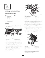
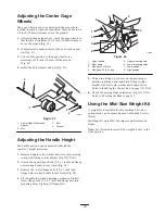
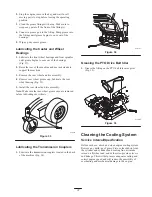
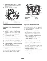
Maintain the air pressure in the front and rear tires as
specified. Check the pressure at the valve stem after every
40 operating hours or monthly, whichever occurs first
(Fig. 36). Check the tires when they are cold to get the
most accurate pressure reading.
Rear Tire Pressure: 12–14 psi (83–97 kPa)
Caster Tire Pressure: 20–24 psi (138–165 kPa)
2
1
m–6367
Figure 36
1.
Rear Tire
2.
Caster tire
Servicing the Fuse
Service Interval/Specification
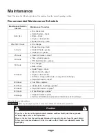
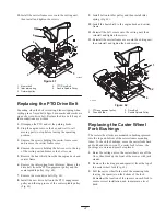
The electrical system is protected by a fuse. It requires no
maintenance. If the fuse blows check component or circuit
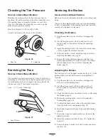
for malfunction or short. To replace the fuse, pull out the
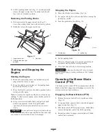
old the fuse (Fig. 37) and push in new fuse.
Fuse: F1–7.5 amp, blade-type
m–5206
1
Figure 37
1.
Fuse 7.5 amp
Servicing the Brakes
Service Interval/Specification
Before each use, check brakes on both a level surface and
slope.
Always set the parking brake when you stop the machine
or leave it unattended. If the parking brake does not hold
securely, an adjustment is required.
Checking the Brakes
1. Park the machine on a level surface, disengage the
PTO.
2. Stop the engine, remove the key, and wait for all
moving parts to stop before leaving the operating
position.
3. Apply the parking brake. The wheels must lock when
you try to push the machine forward.
4. If the wheels do not lock, adjust the brakes. Refer to
Adjusting the Brakes on page 32.
5. Release the brake and press upper control bar very
lightly, approximately 1/2 inch (13 mm). The wheels
should rotate freely, if not; refer to Adjusting the
Brake, page 32.
Adjusting the Brakes
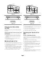
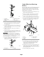
The brake lever is on the upper control bar (Fig. 16). If the
parking brake does not hold securely, an adjustment is
required.
1. Park the machine on a level surface, disengage the
PTO, and set the parking brake.
2. Stop the engine, remove the key, and wait for all
moving parts to stop before leaving the operating
position.
3. Check the brake before you adjust it; refer to Checking
the Brakes, page 32.
4. Release the parking brake; refer to Releasing the
Parking Brake, page 21.
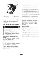
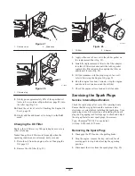
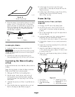
5. To adjust the brake remove the cotter pin and washer
from the brake lever and trunnion (Fig. 38).
6. Rotate the wingnut clockwise to increase the braking
pressure.
7. Rotate the wingnut counterclockwise to decrease the
braking pressure.
8. Install the trunnion into hole F (Fig. 38). Tighten the
wing nut.
9. Secure trunnion to brake lever with washer and cotter
pin (Fig. 38).


