background image

Operating the Mower Blade
Control Knob (PTO)

The blade control knob (PTO) is used in conjunction with
the Operator Presence Control (OPC) levers to engage and
disengage the mower blades.

Engaging the Mower Blades (PTO)

1.

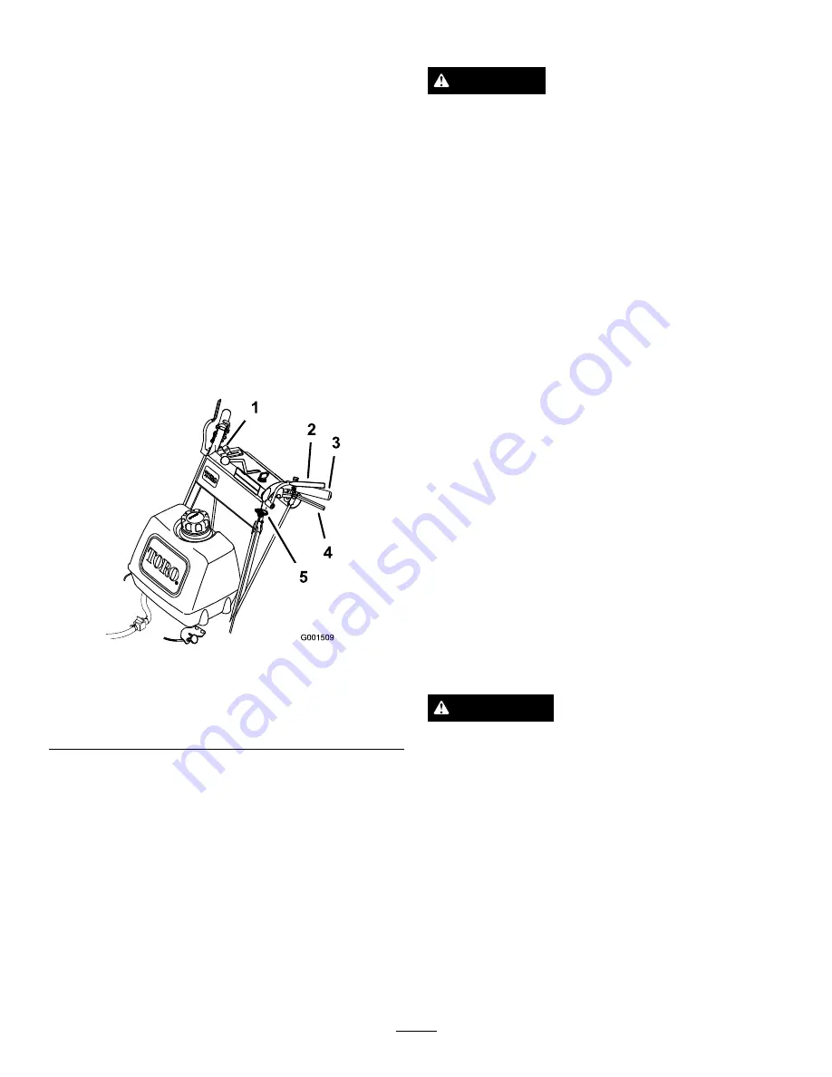
To engage blades, squeeze the Operator Presence
Control (OPC) levers against handle grips (Figure 12).

2.

Pull blade control knob (PTO) up. Hold the OPC
levers against handle grip.

Note:

The engine will kill if the OPC levers are

released with the mower running and the speed control
lever is not in neutral.

3.

Restart the engine and repeat the procedure to engage
the mower blades if the operator presence control
(OPC) levers are released.

Figure 12

1.

Throttle lever

4.

Drive Lever

2.

Operator Presence
Control levers (OPC)

5.

Blade control knob (PTO)

3.

Handle

Disengaging the Mower Blades (PTO)

The mower blades can be disengaged by one of the following
steps.

1.

Push the blade control knob (PTO) down to off
(Figure 12).

2.

Releasing the Operator Presence Control (OPC) levers
will kill the engine and stop the blades (Figure 12) with
the blade control lever engaged.

The Safety Interlock System

CAUTION

If safety interlock switches are disconnected or
damaged the machine could operate unexpectedly
causing personal injury.

Do not tamper with the interlock switches.

Check the operation of the interlock switches
daily and replace any damaged switches before
operating the machine.

Understanding the Safety Interlock
System

The safety interlock system is designed to prevent the mower
from starting unless:

The blade control knob (PTO) is pushed off.

The speed control lever is in neutral.

The safety interlock system is designed to kill the engine
when:

The Operator Presence Control (OPC) levers are released
with the mower engaged and/or the speed control is out
of neutral.

The speed control lever is shifted out of neutral without
holding OPC levers or with the brake engaged.

The blade control knob (PTO) is pulled up without
holding the OPC levers.

Testing the Safety Interlock System

Service Interval:

Before each use or daily

Test the safety interlock system before you use the machine
each time. If the safety system does not operate as described,
have an Authorized Service Dealer repair the safety system
immediately.

WARNING

While testing the safety interlock system, the
machine may move forward and cause personal
injury or property damage.

Perform the safety interlock test in an open area.

Ensure no one is standing in front of the
machine while performing the safety interlock
test.

1.

Set the neutral locks and place speed control lever in
neutral.

2.

Start the engine; refer to Starting and Stopping the
Engine.

3.

Without holding the Operator Presence Control (OPC)
levers, pull the blade control knob (PTO) up. The
engine should kill.

16

Summary of Contents for 30934

Page 1: ...rive with 36in or 48in TURBO FORCE Cutting Unit Model No 30934 Serial No 313000001 and Up Model No 30938 Serial No 313000001 and Up Model No 39934 Serial No 313000001 and Up Model No 39938 Serial No 313000001 and Up G017540 Register at www Toro com Original Instructions EN 3376 461 A ...

Page 2: ...garding the US Environmental Protection Agency EPA and the California Emission Control Regulation of emission systems maintenance and warranty Replacements may be ordered through the engine manufacturer Introduction This rotary blade lawn mower is intended to be used by residential homeowners or professional hired operators It is designed primarily for cutting grass on well maintained lawns on res...

Page 3: ...17 Bringing the Machine to Neutral Position 17 Stopping the Machine 17 Pushing the Machine by Hand 17 Adjusting the Flow Baffle 18 Positioning the Flow Baffle 18 Transporting Machines 19 Side Discharging or Mulching the Grass 19 Adjusting the Height of Cut 19 Adjusting the Caster Position 20 Adjusting the Handle Height 21 Height of Cut Chart 22 Maintenance 23 Recommended Maintenance Schedule s 23 ...

Page 4: ...it is the owner s responsibility to explain this material to them Become familiar with the safe operation of the equipment operator controls and safety signs All operators and mechanics should be trained The owner is responsible for training the users Never let children or untrained people operate or service the equipment Local regulations may restrict the age of the operator The owner user can pr...

Page 5: ... in handling gasoline Gasoline is extremely flammable and the vapors are explosive Extinguish all cigarettes cigars pipes and other sources of ignition Use only an approved fuel container Never remove fuel cap or add fuel with the engine running Allow engine to cool before refueling Never refuel the machine indoors Never store the machine or fuel container where there is an open flame spark or pil...

Page 6: ...sed with unapproved attachments Check carefully for overhead clearances i e branches doorways electrical wires before operating under any objects and do not contact them Slope Operation All slopes and ramps require extra caution If you feel uneasy on a slope do not mow it Remove obstacles such as rocks tree limbs etc from the mowing area Watch for holes ruts or bumps Tall grass can hide obstacles ...

Page 7: ... degrees Use the slope chart to determine the degree of slope of hills before operating Do not operate this machine on a slope greater than 20 degrees Fold along the appropriate line to match the recommended slope 2 Align this edge with a vertical surface a tree building fence pole etc 3 Example of how to compare slope with folded edge 7 ...

Page 8: ...ecal that is damaged or lost 1 403005 66 1340 95 5537 1 Read the Operator s Manual for instructions on operating the cutting blade 3 Pull back to disengage 2 Push forward to engage 98 0776 98 3296 For Models with 2 Blade Mower Decks 98 5130 1 Warning read the Operator s Manual for instructions on torquing the blade bolt nut to 75 80 ft lb 102 106 N m 98 5954 8 ...

Page 9: ...ve gases can cause blindness and other injuries 3 Caustic liquid chemical burn hazard 8 Battery acid can cause blindness or severe burns 4 Wear eye protection 9 Flush eyes immediately with water and get medical help fast 5 Read the Operator s Manual 10 Contains lead do not discard 99 3943 1 Engine 103 2103 103 2076 104 8569 105 4109 105 4110 106 2733 1 Fast 3 Slow 2 Continuous variable setting 9 ...

Page 10: ...nufacturer 110 2067 110 2068 1 Read the Operator s Manual 115 4212 1 Hydraulic oil level 3 Warning do not touch the hot surface 2 Read the Operator s Manual 106 2738 1 Park 4 Engine stop 7 Fast 10 Neutral 2 Drive 5 Engine run 8 Continuous variable setting 3 Neutral 6 Warning wear ear protection 9 Slow 10 ...

Page 11: ...r blades with the OPC levers pressed against the handles Pull the knob up to engage the blades and down to disengage the blades Figure 5 1 Throttle control 6 Handle 2 Speed control lever 7 Drive Lever 3 Ignition switch 8 Blade control knob PTO 4 Neutral lock 9 Choke 5 Operator Presence Control levers OPC 10 Fuel shut off valve Ignition Switch This switch is used in conjunction with recoil starter ...

Page 12: ... blends of gasoline such as E15 or E85 with more than 10 ethanol by volume Performance problems and or engine damage may result which may not be covered under warranty Do Not use gasoline containing methanol Do Not store fuel either in the fuel tank or fuel containers over the winter unless a fuel stabilizer is used Do Not add oil to gasoline DANGER In certain conditions gasoline is extremely flam...

Page 13: ...d starting Important Do not use fuel additives containing methanol or ethanol Add the correct amount of gas stabilizer conditioner to the gas Note A fuel stabilizer conditioner is most effective when mixed with fresh gasoline To minimize the chance of varnish deposits in the fuel system use fuel stabilizer at all times Filling the Fuel Tank 1 Shut the engine off and set the parking brake 2 Clean a...

Page 14: ... lever to neutral 4 Move the drive levers to neutral and set the neutral locks 5 Set the parking brake 6 Turn the ignition key to the run position Figure 5 7 To start a cold engine move the throttle control midway between the fast and slow positions 8 To start a warm engine move the throttle control to the fast position 9 Pull the choke knob if the engine is cold Figure 5 Note A warm or hot engine...

Page 15: ...nded Setting the Neutral Lock 1 Squeeze the drive levers back until an increase in force is felt 2 Place thumbs on the upper part of the locks and move them back Figure 10 Figure 10 1 Handle 4 Drive lever 2 Neutral lock 5 Full speed forward 3 Neutral position 6 Reverse position Releasing the Neutral Lock 1 Squeeze the drive levers back until an increase in force is felt 2 Place thumbs on the upper...

Page 16: ... the operation of the interlock switches daily and replace any damaged switches before operating the machine Understanding the Safety Interlock System The safety interlock system is designed to prevent the mower from starting unless The blade control knob PTO is pushed off The speed control lever is in neutral The safety interlock system is designed to kill the engine when The Operator Presence Co...

Page 17: ...rake when you stop the machine 1 Squeeze the drive levers to neutral position 2 Set the neutral locks Refer to Operating Neutral Locks 3 Move speed control lever to neutral position Note The speed control lever can also be used to bring the mower to neutral position and then set the neutral locks Stopping the Machine 1 To stop the machine squeeze the drive levers to neutral position and engage neu...

Page 18: ...before leaving the operating position 3 To adjust the baffle loosen the nut Figure 15 4 Adjust the baffle and nut in the slot to the desired discharge flow and tighten the nut g012676 1 2 Figure 15 1 Slot 2 Nut Positioning the Flow Baffle The following figures are only recommendations for use Adjustments will vary by grass type moisture content and height of grass Note If the engine power draws do...

Page 19: ...s and thrown debris will cause injury or death Never remove the grass deflector from the mower because the grass deflector routes material down toward the turf If the grass deflector is ever damaged replace it immediately Never put your hands or feet under the mower Never try to clear discharge area or mower blades unless you release the bail and the power take off PTO is off Rotate the ignition k...

Page 20: ...emove the drive wheels 4 Remove the drive wheels 5 Loosen but do not remove the 2 top axle bolts Figure 20 6 Remove the 2 lower axle bolts Figure 20 Figure 20 1 Top axle bolt 2 Lower axle bolt 7 Raise or lower the mounting bracket so that you can install the 2 axle adjustment bolts in the desired hole location Figure 20 A tapered punch can be used to help align the holes 8 Tighten all 4 bolts 9 In...

Page 21: ...re 23 4 Pivot handle to desired operating position and install lower flange bolts 3 8 x 1 inch and flange nuts into mounting holes Tighten all flange bolts Figure 23 1 Control rod fitting 6 High position 2 Lower mounting holes 7 Lower position 3 Rear frame 8 Upper mounting hole 4 Lower flange bolt 3 8 x 1 inch 9 Handle 5 Upper flange bolt 3 8 x 1 1 4 inches 10 Flange nut 3 8 inch 5 Adjust the cont...

Page 22: ... 1 7 8 inch 48 mm 2 1 8 inch 54 mm 2 3 8 inch 60 mm 2 5 8 inch 67 mm 2 7 8 inch 73 mm C 2 0 2 1 8 inch 55 mm 2 3 8 inch 60 mm 2 5 8 inch 67 mm 2 7 8 inch 73 mm 3 1 8 inch 79 mm C 2 1 2 1 4 inch 57 mm 2 1 2 inch 64 mm 2 3 4 inch 70 mm 3 inch 76 mm 3 1 4 inch 83 mm C 3 0 2 1 2 inch 64 mm 2 3 4 inch 70 mm 3 inch 76 mm 3 1 4 inch 83 mm 3 1 2 inch 89 mm D 2 1 2 3 8 inch 61 mm 2 5 8 inch 67 mm 2 7 8 inc...

Page 23: ...nt Check the tire pressure Check the belts Check the mower belt tension Every 100 hours Grease the blade engagement bellcrank Change the engine oil Check the spark plugs Check and clean engine cooling fins and shrouds Check the hydraulic hoses Every 200 hours Replace the paper air cleaner element Change the oil filter Replace the fuel filter Replace the fuel vent filter Change the hydraulic filter...

Page 24: ...r wheels and caster pivot Lubricate the front wheel bearings and front spindles Figure 24 Greasing the Mower Belt Idler Service Interval Every 50 hours Grease the mower belt idler Grease the fitting on the mower belt idler arm pivot Figure 24 Note Remove the mower deck cover to access the grease fitting for the mower belt idler arm Greasing the Pump Control and Bell Crank Service Interval Every 50...

Page 25: ...it thoroughly 2 Dry the element by squeezing it in a clean cloth Important Replace the foam element if it is torn or worn Servicing the Paper Air Cleaner Element 1 Do not clean the paper filter replace it Figure 25 2 Inspect the element for tears an oily film or damage to the rubber seal 3 Replace the paper element if it is damaged Installing the Foam and Paper Elements Important To prevent engine...

Page 26: ...hine so that the drain side is slightly lower than the opposite side to assure the oil drains completely 2 Disengage the PTO and set the parking brake 3 Stop the engine remove the key and wait for all moving parts to stop before leaving the operating position 4 Slide the drain hose over the oil drain valve 5 Place a pan below the drain hose Rotate oil drain valve to allow oil to drain Figure 28 6 ...

Page 27: ...ssary Type Champion RCJ8Y or equivalent Air Gap 0 030 inch 0 75 mm Removing the Spark Plugs 1 Disengage the PTO and set the parking brake 2 Stop the engine remove the key and wait for all moving parts to stop before leaving the operating position 3 Disconnect the wires from the spark plugs Figure 30 1 Figure 30 1 Spark plug wire spark plug 4 Clean around the spark plugs to prevent dirt from fallin...

Page 28: ...a spark may ignite the gasoline fumes Draining the Fuel Tank 1 Park the machine on a level surface to assure fuel tank drains completely Then disengage the power take off PTO set the parking brake and turn the ignition key to off Remove the key 2 Close the fuel shut off valve at the fuel tank Figure 32 3 Squeeze the ends of the hose clamp together and slide it up the fuel line away from fuel filte...

Page 29: ... the hose clamps together and slide them away from the filter Figure 33 Figure 33 1 Hose clamp 3 Filter 2 Fuel line 5 Remove the filter from the fuel lines 6 Install a new filter and move the hose clamps close to the filter 7 Open fuel shut off valve at fuel tank Figure 32 8 Check for fuel leaks and repair if needed 9 Wipe up any spilled fuel Servicing the Fuel Vent System Service Interval Every 2...

Page 30: ...on 2 Yoke 5 Jam nut 3 Speed control crank 6 Pull the speed control lever back to neutral 7 Check to make sure the safety switch is depressed and there is a 5 16 inch 8 mm space between the actuating tab and the switch Figure 36 8 If needed adjust switch location to create the 5 16 inch 8 mm space Figure 36 Figure 36 1 Actuating tab 3 Safety switch 2 5 16 inch 8 mm space Adjusting the Neutral Contr...

Page 31: ...37 12 Turn the adjusting bolt approximately 1 4 turn clockwise if the wheel is turning in reverse or turn the bolt approximately 1 4 turn counter clockwise if the wheel is turning forward Figure 37 13 Release the drive lever to the forward drive position and squeeze back into the neutral position Check to see if the wheel stops If not repeat the above adjustment procedure 14 After adjustments are ...

Page 32: ...l position 13 Hold the OPC levers down Note The OPC levers must be held down whenever the speed control lever is out of the neutral position or the engine will kill 14 Make sure the speed control lever is in the neutral position and the tire does not rotate 15 Repeat the adjustment if needed Figure 39 1 Hydro control linkage 3 Rear adjusting nut 2 Front adjustingnut 4 Control arm Note If inconsist...

Page 33: ...to be adjusted Adjusting the Control Rod 1 Adjust the rod length by releasing the drive lever and removing the hairpin cotter pin and clevis pin Rotate the rod in the rod fitting Figure 42 2 Lengthen the control rod if the tire is turning in reverse and shorten the rod if the tire is turning forward 3 Rotate the rod several turns if the tire is rotating fast Then adjust the rod in 1 2 turn increme...

Page 34: ...e operating position 3 For a heavier drive setting relocate the spring anchor links to either the medium or heavy duty positions Figure 45 The spring anchor links are attached to the upper rear corner of the hydro drive shields on the left and right sides of the machine Note In the medium or heavy duty positions the drive lever forces at the upper handle will also be increased Figure 45 1 Spring a...

Page 35: ... fan housing Figure 47 Figure 47 1 Air intake screen 4 Bolt 2 Fan housing 5 Nut 3 Recoil starter Brake Maintenance Servicing the Brake Before each use check the parking brake for proper operation Always set the parking brake when you stop the machine or leave it unattended If the parking brake does not hold securely adjust it Checking the Parking Brake 1 Move the machine onto a level surface 2 Dis...

Page 36: ...be adjusted when the belt tension or the brake linkage is adjusted 1 Disengage the blade control PTO lever and set the parking brakes 2 Stop the engine and wait for all moving parts to stop before leaving the operating position 3 Remove the knobs and the belt cover on the mower 4 Remove the idler pulley and the worn belt 5 Install the new mower belt 6 Install the idler pulley 7 Engage the blade co...

Page 37: ... 50 hours Check the mower belt tension Important The brake needs to be adjusted when the belt tension or the brake linkage is adjusted Important The belt must be tight enough to not slip during heavy loads while cutting grass Over tensioning the belt will reduce the spindle bearing life the belt life and the idler pulley life The belt must be tight enough so it does not slip during heavy loads whi...

Page 38: ...leaving the operating position 3 Loosen the locknut on the turnbuckle Figure 54 4 Rotate the turnbuckle toward the rear of the mower to increase the tension on the belt Rotate the turnbuckle toward the front of the mower to decrease the tension on the belt Figure 54 Note The proper mower belt tension is 10 15 lbf 44 67 N with the belt deflected 1 2 inch 13 mm halfway between the pulleys Figure 53 ...

Page 39: ...rake Figure 56 1 Belt guide Adjusting the PTO Engagement Linkage The PTO engagement linkage adjustment is located beneath the front left hand corner of the engine deck 1 Disengage the blade control PTO lever and set the parking brakes 2 Stop the engine and wait for all moving parts to stop before leaving the operating position 3 Engage the blade control lever PTO 4 Adjust the linkage length to whe...

Page 40: ...usting the PTO Safety Switch 1 Disengage the blade control PTO lever and set the parking brakes 2 Stop the engine and wait for all moving parts to stop before leaving the operating position 3 Disengage the blade control lever PTO Make sure the assist arm is against the front assist stop arm 4 If needed adjust the blade safety switch by loosening the bolts holding the switch bracket Figure 59 5 Mov...

Page 41: ... until it reaches the hot level of the baffle Note The fluid level should be to the top of the hot level of the baffle when the fluid is warm Figure 60 9 Install cap on filler neck WARNING Hydraulic fluid escaping under pressure can penetrate skin and cause injury If hydraulic fluid is injected into the skin it must be surgically removed within a few hours by a doctor familiar with this type of in...

Page 42: ...arge pump is primed 1 Disengage the PTO and set the parking brake 2 Stop the engine and wait for all moving parts to stop before leaving the operating position 3 Raise the rear of the machine up onto jack stands high enough to raise the drive wheels off the ground 4 Check the hydraulic fluid level 5 Start the engine and move the throttle control to the full throttle position Move the speed control...

Page 43: ...aulic system Mower Deck Maintenance Servicing the Cutting Blades To ensure a superior quality of cut keep the blades sharp For convenient sharpening and replacement you may want to keep extra blades on hand WARNING A worn or damaged blade can break and a piece of the blade could be thrown into the operator s or bystander s area resulting in serious personal injury or death Inspect the blade period...

Page 44: ...with a new blade Never file or create sharp notches in the edges or surfaces of blade Removing the Blades Replace the blades if you hit a solid object or if the blades are out of balance or bent To ensure optimum performance and continued safety conformance of the machine use genuine Toro replacement blades Replacement blades made by other manufacturers may result in non conformance with safety st...

Page 45: ...the operating position and then set the parking brakes 3 If necessary adjust the spring mounting bolts so that the blade brake pad rubs against both sides of the pulley groove Figure 69 4 Adjust the nut at the end of the blade brake rod until there is 1 8 3 16 inch 3 mm 5 mm between the nut and spacer Figure 69 5 Engage the blades Ensure the blade brake pad no longer contacts the pulley groove Fig...

Page 46: ... the machine refer to Greasing and Lubrication in Lubrication page 24 6 Change the crankcase oil refer to Servicing the Engine in 7 Check the tire pressure refer to Checking the Tire Pressure in Drive System Maintenance page 30 8 For long term storage A Add stabilizer conditioner additive to fuel in the tank B Run engine to distribute conditioned fuel through the fuel system 5 minutes C Stop engin...

Page 47: ...or stale fuel is in the fuel system 8 Contact an Authorized Service Dealer 1 Engine load is excessive 1 Reduce the ground speed 2 Oil level in the crankcase is low 2 Add oil to the crankcase Engine overheats 3 Cooling fins and air passages under the engine blower housing are plugged 3 Remove the obstruction from the cooling fins and air passages 1 Shift lever is in neutral 1 Move the shift lever t...

Page 48: ...eck the belt tension 2 Mower deck belt is broken 2 Install new deck belt 3 Mower deck belt is off pulley 3 Inspect the belt and replace if damaged Check the pulleys and idlers and adjust the belt tension Blades do not rotate 4 Broken or missing idler spring 4 Replace the spring 48 ...

Page 49: ...Schematics Electrical Schematic Rev Hydraulic Schematic Rev 49 ...

Page 50: ...Notes 50 ...

Page 51: ...Notes 51 ...

Page 52: ... item 3 to use the 24 hour Toro Dealer locator system 2 Bring the product and your proof of purchase sales receipt to the Service Dealer The dealer will diagnose the problem and determine if it is covered under warranty 3 If for any reason you are dissatisfied with the Service Dealer s analysis or with the assistance provided contact us at RLC Customer Care Department Toro Warranty Company 8111 Ly...

Reviews: